Flow direction (HL)
The flow direction parameter specifies the
direction in which most of the links must point. If the flow
direction is to the top or to the bottom, the node levels are
oriented horizontally and the links mostly vertically. If the
flow direction is to the left or to the right, the node levels
are oriented vertically and the links mostly horizontally.
If the flow direction is to the bottom,
the nodes of the level with index 0 are placed at the top border
of the drawing. The nodes with level index 0 are usually the root
nodes of the drawing (that is, the nodes without incoming links).
If the flow direction is to the top, the nodes with level index 0
are placed at the bottom border of the drawing. If the flow
direction is to the right, the nodes are placed at the left
border of the drawing.
Flow directions
To specify the flow direction towards
the bottom:
In CSS
Add to the
GraphLayout
section:
flowDirection: "Bottom";
In Java
In Java, use the method:
void setFlowDirection(int direction)
The valid values for the flow direction
are:
IlvDirection.Right(the default)IlvDirection.LeftIlvDirection.BottomIlvDirection.Top
In CSS, you omit the prefix
IlvDirection
when specifying the value of the flow direction.
Leveling strategy (HL)
The layout algorithm partitions the nodes into levels (see A brief description of the HL algorithm).
The leveling strategy specifies how the levels are calculated.
Besides the leveling strategy, layout constraints (see Layout constraints for HL), level indexes
(see For experts: more indexes (HL)) as well as
the incremental mode (see Incremental mode with HL) also affect the
way the levels are calculated. If the incremental mode is
disabled, the leveling strategy determines the levels of all
nodes that are not subject to layout constraints and level index
specifications.
Leveling strategies
To specify the leveling strategy:
In CSS
Add to the
GraphLayout
section:
levelingStrategy: "OPTIMAL";
In Java
In Java™ , use the method:
void setLevelingStrategy(int strategy)
The valid values for the leveling strategy
are:
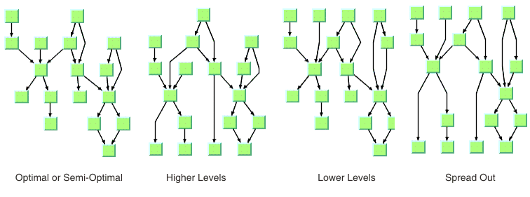
IlvHierarchicalLayout.SEMI_OPTIMAL(the default)This value produces often the same result as the optimal strategy, but it is quicker. The layout algorithm uses a heuristic to minimize the sum of level distances for all edges. It pulls root nodes to the highest-numbered possible level and leaf nodes to the lowest-numbered possible level.IlvHierarchicalLayout.OPTIMALThis value uses an algorithm that minimizes the sum of level distances for all edges. The optimal strategy is slower than the other strategies, but often produces the best result.IlvHierarchicalLayout.HIGHER_LEVELSNodes have a tendency to use the possible level with the highest level number. All leaf nodes are at the highest-numbered level. All root nodes are pulled to high-numbered levels as much as possible.IlvHierarchicalLayout.LOWER_LEVELSNodes have a tendency to use the possible level with the lowest level number. All root nodes are at level 0. All leaf nodes are pulled to low-numbered levels as much as possible.IlvHierarchicalLayout.SPREAD_OUTThis strategy is a combination of the lower-level and higher-level strategies. All root nodes are at level 0. All leaf nodes are at the highest-numbered level. All inner nodes are at balanced positions.
In CSS, you omit the prefix
IlvHierarchicalLayout
when specifying the value of the leveling strategy.
Level justification (HL)
If the layout uses horizontal levels, the
nodes of the same level are placed approximately at the same
y-coordinate. The nodes can be justified, depending on whether
the top border, the bottom border, or the center of all nodes of
the same level have the same y-coordinate.
If the layout uses vertical levels, the
nodes of the same level are placed approximately at the same
x-coordinate. The nodes can be justified to be aligned at the
left border, at the right border, or at the center of the nodes
that belong to the same level.
To specify the level justification
towards the top:
In CSS
Add to the
GraphLayout
section:
levelJustification: "Top";
In Java
Use the method:
void setLevelJustification(int justification)
If the flow direction is to the top or to
the bottom, the valid values for the level justification are:
IlvDirection.TopIlvDirection.BottomIlvDirection.Center(the default)
Level justification for horizontal
levels
If the flow direction is to the left or to
the right, the valid values for the level justification are:
IlvDirection.LeftIlvDirection.RightIlvDirection.Center(the default)
In CSS, you omit the prefix
IlvDirection
when specifying the value of the flow direction.
Level justification for vertical
levels
Link style (HL)
The layout algorithm positions the nodes
and routes the links. To avoid overlapping nodes and links, it
creates bend points for the shapes of links. The link style
parameter controls the position and number of bend points. The
link style can be set globally, in which case all links have the
same shape, or locally on each link such that different link
shapes occur in the same drawing.
Link styles
Link style and link shapes
Link styles work only when you use links that can be reshaped.
Subclasses of IlvPolylineLinkImage or of IlvSplineLinkImage, (e.g.,
IlvGeneralLink
) can be reshaped. Furthermore, link styles work only if free
link connectors are installed. Free link connectors are
subclasses of IlvFreeLinkConnector. If you use a
diagram component, the free link connectors are automatically
installed when needed unless specified differently. If you call
layout on an
IlvGrapher
directly in Java, the layout algorithm may raise an IlvInappropriateLinkException if links
are neither a subclass of IlvPolylineLinkImage nor of IlvSplineLinkImage, or if connectors are
not a subclass of
IlvFreeLinkConnector
. In this case, you can use the methods
EnsureAppropriateLinkTypes
,
EnsureAppropriateLinkConnectors
or
EnsureAppropriateLinks
defined in the class IlvGraphLayoutUtil to replace
inappropriate links or link connectors automatically, either
before layout or when the IlvInappropriateLinkException is caught.
For details on these methods, see the Java
API Reference Manual.For details on the graph model, see Using
the graph model.
Global link style
To set the global link style:
In CSS
Add to the
GraphLayout
section:
globalLinkStyle: "POLYLINE_STYLE";
In Java
Use the method:
void setGlobalLinkStyle(int style)
The valid values for the link style are:
IlvHierarchicalLayout.POLYLINE_STYLEAll links get a polyline shape. A polyline shape consists of a sequence of line segments that are connected at bend points. The line segments can be turned into any direction. This value is the default value.IlvHierarchicalLayout.ORTHOGONAL_STYLEAll links get an orthogonal shape. An orthogonal shape consists of orthogonal line segments that are connected at bend points. An orthogonal shape is a polyline shape where the segments can be turned only in directions of 0, 90, 180 or 270 degrees.IlvHierarchicalLayout.STRAIGHT_LINE_STYLEAll links get a straight-line shape. All intermediate bend points (if any) are removed. This value often causes overlapping nodes and links.IlvHierarchicalLayout.NO_RESHAPE_STYLENone of the links is reshaped in any manner. Note, however, that unlike fixed links, the links are not ignored completely. They are still used to calculate the leveling.IlvHierarchicalLayout.MIXED_STYLEEach link can have a different link style. The style of each individual link can be set such that different link shapes can occur in the same graph.
In CSS, you omit the prefix
IlvHierarchicalLayout
when specifying the value of the link style.
Individual link style
All links have the same style of shape unless the global link
style is
MIXED_STYLE
. Only when the global link style is
MIXED_STYLE
can each link have an individual link style.
Different link styles mixed in the
same drawing
To specify the style of an individual
link:
In CSS
First set the global link style to
MIXED-STYLE, then specify a rule that selects the link, for
instance:
GraphLayout {
   globalLinkStyle: "MIXED_STYLE";
}
#link1
{
  LinkStyle: "ORTHOGONAL_STYLE";
}
In Java
Use the methods:
void setLinkStyle(Object link, int style)
int getLinkStyle(Object link)
In this case, the link argument must be a graphic link
(subclass of
IlvLinkImage
).
The valid values for the link style of
local links are the same as for the global link style:
IlvHierarchicalLayout.POLYLINE_STYLEIlvHierarchicalLayout.ORTHOGONAL_STYLEIlvHierarchicalLayout.STRAIGHT_LINE_STYLEIlvHierarchicalLayout.NO_RESHAPE_STYLE
Note
The link style of a Hierarchical Layout graph requires links
in an IlvGrapher that can be reshaped. Links
of type IlvLinkImage, IlvOneLinkImage, IlvDoubleLinkImage, IlvOneSplineLinkImage, and IlvDoubleSplineLinkImage cannot be
reshaped. You should use the class IlvPolylineLinkImage or IlvSplineLinkImage instead.
Connector style (HL)
The layout algorithm positions the end
points of links (the connector pins) at the nodes automatically.
The connector style parameter specifies how these end points are
calculated.
Connector styles
To specify the connector style:
In CSS
Add to the
GraphLayout
section:
connectorStyle: "CLIPPED_PINS";
In Java
Use the method:
void setConnectorStyle(int style)
The valid values for
style
are:
IlvHierarchicalLayout.CENTERED_PINSThe end points of the links are placed in the center of the border where the links are attached. This option is well-suited for polyline links and straight-line links. It is less suited for orthogonal links, because orthogonal links can look ambiguous in this style.IlvHierarchicalLayout.CLIPPED_PINSEach link pointing to the center of the node is clipped at the node border. The connector pins are placed at the points on the border where the links are clipped. This option is well-suited for polyline links without port specifications. It must not be used if a port side for any link is specified.IlvHierarchicalLayout.EVENLY_SPACED_PINSThe connector pins are evenly distributed along the node border. This style guarantees that the end points of the links do not overlap. It is the best style for orthogonal links and works well for other link styles.IlvHierarchicalLayout.AUTOMATIC_PINSThe connector style is selected automatically depending on the link style. If any of the links has an orthogonal style or if any of the links has a port side specification, the algorithm chooses evenly spaced connectors. If all the links are straight, it chooses centered connectors. Otherwise, it chooses clipped connectors.
In CSS, you omit the prefix
IlvHierarchicalLayout
when specifying the value of the connector style.
Note
The connector style parameter requires link connectors at the
nodes of an IlvGrapher that allow connector pins to
be placed freely at the node border. It is recommended that
you use IlvFreeLinkConnector for link connectors
to be used in combination with
IlvGrapher
objects. If you use a diagram component, the free link
connectors are automatically installed when needed, unless
specified differently.
End point mode (HL)
Normally, the layout algorithm is free to choose the
termination points of each link. However, if fixed-link
connectors are used (for instance, IlvPinLinkConnector), the user can
specify that the current fixed termination pin of a link must
be used.
The layout algorithm provides two end
point modes. You can set the end point mode globally, in which
case all end points have the same mode, or locally on each link,
in which case different end point modes occur in the same
drawing.
Global end point mode
To set the global end point mode:
In CSS
Add to the
GraphLayout
section:
globalOriginPointMode: "FIXED_MODE";
globalDestinationPointMode: "FIXED_MODE";
In Java
Use the methods:
void setGlobalOriginPointMode(int mode);
void setGlobalDestinationPointMode(int mode);
The valid values for
mode
are:
IlvLinkLayout.FREE_MODE(the default)The layout is free to choose the appropriate position of the connection point on the origin/destination node.IlvLinkLayout.FIXED_MODEThe layout must keep the current position of the connection point on the origin/destination node.IlvLinkLayout.MIXED_MODEEach link can have a different end point mode.
In CSS, you omit the prefix
IlvHierarchicalLayout
when specifying the value of the end point mode.
The connection points are
automatically considered as fixed if they are connected to
grapher pins.
Individual end point mode
All links have the same end point mode unless the global end
point mode is
IlvLinkLayout.MIXED_MODE
. Only when the global end point mode is set to
MIXED_MODE
can each link have an individual end point mode.
To set the end point mode of an
individual link:
In CSS
First set the global point modes to
MIXED_MODE, then specify a rule that selects the link, for
instance:
LinkLayout {
   globalOriginPointMode      : "MIXED_MODE";
   globalDestinationPointMode : "MIXED_MODE";
}
#link1
{
  OriginPointMode            : "FIXED_MODE";
  DestinationPointMode       : "FIXED_MODE";
}
In Java
Use the methods:
void setOriginPointMode(Object link, int mode);
int getOriginPointMode(Object link);
void setDestinationPointMode(Object link, int mode);
int getDestinationPointMode(Object link);
The valid values for
mode
are:
IlvLinkLayout.FREE_MODE(the default)IlvLinkLayout.FIXED_MODE
The connection points are
automatically considered as fixed if they are connected to
grapher pins.
Using a link connection box interface (HL)
By default, the connector style determines
how the connection points of the links are distributed on the
border of the bounding box of the nodes, symmetrically with
respect to the middle of each side. Sometimes it can be necessary
to place the connection points on a rectangle smaller or larger
than the bounding box. For instance, it can happen when labels
are displayed below or above nodes.
You can modify the position of the connection points of the
links by providing a class that implements the IlvLinkConnectionBoxInterface. An example
for the implementation of a link connection box interface is in
Link connection box. To set a link
connection box interface in Java, use the method:
The link connection box interface provides
each node with a link connection box and tangential shift
offsets. The Hierarchical Layout uses the link connection box but
does not use the tangential offsets.
The following figure illustrates the
effects of customizing the connection box. On the left is the
result without any connection box interface. The picture on the
right shows the effect if the connection box interface returns
the dashed rectangle for the blue node.
Effect of connection box interface
Using a link clipping interface (HL)
By default, the Hierarchical Layout places
the connection points of links at the border of the bounding box
of the nodes. If the node has a non-rectangular shape such as a
triangle, rhombus, or circle, you may want the connection points
to be placed exactly on the border of the shape. This can be
achieved by specifying a link clip interface. The link clip
interface allows you to correct the calculated connection point
so that it lies on the border of the shape. The following figure
shows an example.
Effect of link clipping interface
You can modify the position of the connection points of the links
by providing a class that implements the IlvLinkClipInterface. An example for the
implementation of a link clip interface is in Link clipping. To set a link clip interface
in Java, use the method:
void setLinkClipInterface(IlvLinkClipInterface interface)
Note
Additionally to the link clip interface, the IlvClippingLinkConnector can be used.
This special link connector updates the clipped connection
points automatically during interactive node movements.
The connector style, the link connection
box interface, and the link clip interface work together in the
following way: by respecting the connector style, the proposed
connection points are calculated on the rectangle obtained from
the link connection box interface (or on the bounding box of the
node, if no link connection box interface was specified). Then,
the proposed connection point is passed to the link clip
interface and the returned connection points are used to connect
the link to the node.
The following figure shows an example of
the combined effect.
Combined effect of link clipping
interface and link connection box
If the links are clipped at the red node
in previous figure (left), they appear unsymmetrical with respect
to the node shape, because the relevant part of the node (here:
the triangle) is not in the center of the bounding box of the
node, but the proposed connection points are calculated with
respect to the bounding box. This can be corrected by using a
link connection box interface to explicitly specify a smaller
connection box for the relevant part of the node (previous
figure, right) such that the proposed connection points are
placed symmetrically around the apex of the triangle of the node.
For experts: thick links (HL)
If evenly spaced pins are used as
connector style, the links can be evenly spaced with respect to
the link center or with respect to the link border. The
difference is only visible when links that connect to the same
node have different widths. For instance, when the link width
indicates the cost or capacity of a flow in the application, many
different link widths can occur.
Figure Using the link width shows the effect of
using different link widths. In the drawing on the left, the
center of the links are evenly distributed at the left node. Each
link has the same space available at the node side. Therefore,
the thick links appear closer to each other than do the thinner
links and the offsets between the link borders are different. In
the drawing on the right, the thick links have more space
available than do the thinner links. The offset between the link
border (at the segments that connect to the left node) is
constant because the link width is considered in the calculation
of the connection points.
Using the link width
To enable the connector calculation to
respect the link width:
In CSS
Add to the
GraphLayout
section for instance the statement:
linkWidthUsed: "true";
In Java
Call:
layout.setLinkWidthUsed(true);
The link width setting is disabled by default. The link width has
no effect if the connector styles
CENTERED_PINS
or
CLIPPED_PINS
are used.
Port sides parameter (HL)
The Hierarchical Layout algorithm produces
a layout where most of the link flows are in the same direction.
If the flow direction is toward the bottom, usually the incoming
links are connected to the top side of the node and the outgoing
links are connected to the bottom side of the node. It is also
possible to specify on which side a link connects to the node.
To simplify the explanations of port sides, port sides are
referred to by the compass directions north,
south, east, and west. The
specified link flow direction is always toward south and the
first level is toward north. If the flow direction is toward the
bottom, north is at the top, south at the bottom, east on the
right, and west on the left side of the drawing. If the flow
direction is toward right, north is on the left, south on the
right, east at the top, and west at the bottom.
The figure Link connections to port sides shows a
drawing where the links connect to the larger middle node at the
specified port sides. A compass icon shows the compass directions
in these drawings.
Link connections to port sides
You can set at which side the link
connects to its source node.
To set at which side the link connects
to its source node:
In CSS
Specify a rule that selects the link,
for instance:
#link1 {
  FromPortSide: "NORTH";
}
In Java
Use the method:
void setFromPortSide(Object link, int side);
In a similar way, you can set at which
side the link connects to its destination node.
To set at which side the link connects
to its destination node:
In CSS
Specify a rule that selects the link,
for instance:
#link1 {
  ToPortSide: "SOUTH";
}
In Java
Use the method:
void setToPortSide(Object link, int side);
The valid values for
side
are:
IlvHierarchicalLayout.UNSPECIFIED(the default)IlvHierarchicalLayout.NORTHIlvHierarchicalLayout.SOUTHIlvHierarchicalLayout.EASTIlvHierarchicalLayout.WEST
In CSS, you omit the prefix
IlvHierarchicalLayout
when specifying the value of the port side.
To retrieve the current choice for a
link, use the methods:
int getFromPortSide(Object link);
int getToPortSide(Object link);
The port sides east and west work well with the orthogonal link
style. Polyline links with these port sides sometimes have
unnecessary bends. Furthermore, if port sides are specified, the
connector style
CLIPPED_PINS
must not be used.
Port index parameter (HL)
Instead of asking the layout algorithm to decide at which point
a link connects to the node border, you can specify where the
links connect to the node. You cannot specify the exact
location, but you can specify the relative location compared to
the connection points of the other links. You can do so by
using a port index. Figure Sample layout with ports and orthogonal
link style shows a sample layout with ports at many nodes.
Links that have the same port index connect at the same point of
the node. The ports are evenly distributed at the node sides, in
a similar way as with the connector style
EVENLY_SPACED_PINS
. The ports are ordered according to their indexes. On the north
and south side of a node, the port indexes increase toward the
east. On the east and west sides of a node, the port indexes
increase toward the south. By using port indexes in this way, it
is easier to rotate a graph by simply changing the flow direction
without updating all the port specifications.
Figure Port index numbering conventions in
relation to flow direction shows how the port indexes depend on
the flow direction.
Port index numbering conventions in
relation to flow direction
Port numbers are normally used in
combination with port sides. Therefore, you must specify how many
ports are available on each side of a node.
To specify the number of ports:
In CSS
Write a rule that selects the node, for
instance:
node.tag1 {
  EastNumberOfPorts: "4";
  WestNumberOfPorts: "4";
  NorthNumberOfPorts: "4";
  SouthNumberOfPorts: "4";
}
Alternatively, you can write:
node.tag1 {
  NumberOfPorts: "EAST,4";
  NumberOfPorts: "WEST,4";
  NumberOfPorts: "NORTH,4";
  NumberOfPorts: "SOUTH,4";
}
Both are equivalent.
In Java
Use the method:
void setNumberOfPorts(Object node, int side, int numberOfPorts);
For example, to use four ports on each
side of a specific node, use the calls:
layout.setNumberOfPorts(node, IlvHierarchicalLayout.EAST, 4);
layout.setNumberOfPorts(node, IlvHierarchicalLayout.WEST, 4);
layout.setNumberOfPorts(node, IlvHierarchicalLayout.NORTH, 4);
layout.setNumberOfPorts(node, IlvHierarchicalLayout.SOUTH, 4);
The node side is specified again by
EAST
,
WEST
,
NORTH
, and
SOUTH
. To retrieve the retrieve the number of ports available at
the node, use the method:
int getNumberOfPorts(Object node, int side);
After the number of ports per side is
specified, you can choose which port each link connects to.
To choose the port side and the port
index for a link:
In CSS
Specify a rule that selects the link,
for instance:
link.tag1 {
  FromPortSide: "NORTH";
  FromPortIndex: "3";
  ToPortSide: "SOUTH";
  ToPortIndex: "3";
}
In Java
To specify the connection at the source
node, use the methods:
void setFromPortSide(Object link, int portSide);
void setFromPortIndex(Object link, int portIndex);
To specify the connection at the
destination node, use the methods:
void setToPortSide(Object link, int portSide);
void setToPortIndex(Object link, int portIndex);
To obtain the current port index of a
link, use the methods:
int getFromPortIndex(Object link);
int getToPortIndex(Object link);
Using the port side and port index
specifications are additional constraints for the layout
algorithm. The more constraints are specified, the more difficult
it is to calculate a layout. Therefore, if too many links have a
specified port index, this resulting layout might have more link
crossings and be less balanced.
Fork link shapes (HL)
If several links start at the same
position and are orthogonally routed, it is sometimes preferred
that the links share the first two link segments. The shape of a
link bundle of this kind looks like a fork. To enable the fork
shape mode for outgoing links, call:
layout.setFromFork(true);
To enable the fork shape mode for
incoming links:
In CSS
Add to the
GraphLayout
section:
fromFork: "true";
toFort: "true";
In Java
Call:
layout.setToFork(true);
These statements are effective only if the links are routed
orthogonally. The fork appears only at those links that start
or end exactly at the same point. Specifying setFromFork(true) by itself does not
force the links to start at the same point. To force links to
start or end at the same point, use the center connector style
(see Connector style (HL)) or specify the same
port for the links (see Port index parameter (HL)).
Fork link shapes
There are two spacing parameters for the
fork shape:
In CSS
Add to the
GraphLayout
section:
minForkSegmentLength: "30.0";
preferredForkAxisLength: "10.0";
In Java
void setMinForkSegmentLength(float length)
Sets the minimum length of the segment
that is directly near the node.
void setPreferredForkAxisLength(float length)
Sets the preferred length of the fork
axis per branch (the second segment next to the node).
If the fork has five branches, the
entire axis has the preferred length five times the specified
parameter. The preferred fork axis length is only a hint for
the layout algorithm. If enough space is available, the
algorithm enlarges the fork axis to avoid unnecessary link
bends. If there is not enough space, the algorithm can
calculate a fork axis that is smaller than the preferred one.
Fork link shapes can sometimes look
ambiguous, in particular when a link starts at the same point
where another link ends. In this case, it is impossible to
recognize whether the arrowhead belongs to one or the other link.
Link priority parameter (HL)
The layout algorithm tries to place the nodes such that all links
are short, point in the flow direction, and do not cross each
other. However, it is not always possible. Often, links cannot
have the same length. If the graph has cycles, some links must be reversed against
the flow direction. If the graph is a nonplanar graph, some links have to cross
each other.
The link priority parameter controls which
links must be selected if long, reversed, or crossing links are
necessary. Links with a low priority are more likely to be
selected than links with a high priority. It does not mean that
low-priority links are always longer, reversed, or crossed. The
graph can have a structure such that no long, reversed, or
crossing links are necessary.
To set the link priority:
In CSS
Specify a rule that selects the link,
for instance:
link.tag1 {
  LinkPriority: "2.0";
}
In Java
Use the methods.
void setLinkPriority(Object link, float priority)
float getLinkPriority(Object link)
The default value of the link priority is
1.0. Negative link priorities are not allowed.
For an example of using the link priority, consider a cycle
A->B->C->D->E->A. It is impossible to lay out this
graph without reversing any link. Therefore, the layout algorithm
selects one link to be reversed. To control which link is
selected, you can give one link a lower priority than the others.
This link is then reversed. In figure Working with link priorities, the bottom
layout shows the use of the link priority. The link C->D was
given the priority 0.5, while all the other links have the
priority 1.0. Therefore C-D is reversed. The top layout in Working with link priorities shows what
happens when all links have the same priority. Link E->A is
reversed.
Working with link priorities
The use of link priorities is important in combination with
ports. Links with “from” ports on the south side and “to” ports
on the north side are preferably laid out opposite to the flow
direction. Such a feedback link can cause parts of the drawing to
tip over. The figure Using link priorities and ports shows an
example. The red link is a feedback link with port
specifications. To obtain the correct result as shown in the
right side of the following figure, you would set the priority of
the feedback link to a very low value.
Using link priorities and ports
Spacing parameters (HL)
The spacing of the layout is controlled by
three kinds of spacing parameters: the minimum offset between
nodes, the minimum offset between parallel segments of links, and
the minimum offset between a node border and a bend point of a
link or a link segment that is parallel to this border. The
offset between parallel segments of links is at the same time the
offset between bend points of links. All three kinds of parameter
occur in both directions: horizontally and vertically.
Spacing parameters
To set the spacing parameters:
In CSS
Add to the
GraphLayout
section:
horizontalNodeOffset: "30.0";
horizontalLinkOffset: "15.0";
horizontalNodeLinkOffset: "20.0";
verticalNodeOffset: "30.0";
verticalLinkOffset: "15.0";
verticalNodeLinkOffset: "20.0";
In Java
- For the horizontal direction, use the methods:
void setHorizontalNodeOffset(float offset)
void setHorizontalLinkOffset(float offset)
void setHorizontalNodeLinkOffset(float offset)
- For the vertical direction, use the methods:
void setVerticalNodeOffset(float offset)
void setVerticalLinkOffset(float offset)
void setVerticalNodeLinkOffset(float offset)
For a layout with horizontal levels (the
flow direction is to the top or to the bottom), the horizontal
node offset is the minimum distance between nodes of the same
level. The vertical node offset is the minimum distance between
nodes of different levels, that is, the minimum distance between
the levels. For non-orthogonal link styles, the horizontal link
offset is basically the minimum distance between bend points of
links. The horizontal node-link offset is the minimum distance
between the node border and the bend point of a link. For
horizontal levels, the vertical link offset and the vertical
node-link offset play a role only if the link shapes are
orthogonal.
Similarly, for a layout with vertical
levels (the flow direction is to the left or to the right), the
vertical node offset controls node distances within the levels.
The horizontal node offset is the minimum distance between the
levels. In this case, the vertical link offset and the vertical
node-link offset always play a role, while the horizontal link
offset and the horizontal node-link offset impact the layout only
with orthogonal links.
For orthogonal links, the horizontal link
offset is the minimum distance between parallel, vertical link
segments. The vertical link offset is the minimum distance
between parallel, horizontal link segments. However, the layout
algorithm cannot always satisfy these offset requirements. If a
node is tiny but has many incident links, it can be impossible to
place the links orthogonally with the specified minimum link
distance on the node border. In this case, the algorithm places
some link segments closer than the specified link offset.
Spacing parameters for orthogonal
links