The IlvGraphLayout class defines a number of
generic features and parameters. These features and parameters
can be used to customize the layout algorithms.
Although the
IlvGraphLayout
class defines the generic parameters, it does not control how
they are used by its subclasses. Each layout algorithm (that is,
each subclass of
IlvGraphLayout
) supports a subset of the generic features and determines the
way in which it uses the generic parameters. When you create your
own layout algorithm by subclassing
IlvGraphLayout
, you decide whether you want to use the features and the way in
which you are going to use them.
The
IlvGraphLayout
class defines the following generic features:
Support by algorithms of generic features and
parameters provides a summary of the generic parameters supported
by each layout algorithm. If you are using one of the subclasses
provided with the graph layout API, check the documentation for
that subclass to know whether it supports a specific parameter and
how it interprets the parameter.
Allowed time
Several layout algorithms can be designed
to stop computation when a user-defined time specification is
exceeded. It can be done for different reasons: for security to
avoid a long computation time on large graphs, or as an upper
limit for algorithms that iteratively improve a current solution
and have no other criteria to stop the computation.
Example of specifying allowed time
To specify that the layout is allowed to
run for 60 seconds:
In CSS
Add to the
GraphLayout
section:
allowedTime: "60000";
In Java
Call:
layout.setAllowedTime(60000)
The time is in milliseconds. The
default value is 32000 (32 seconds).
If you subclass IlvGraphLayout, use the following method
to know whether the specified time was exceeded:
boolean isLayoutTimeElapsed()
To indicate whether a subclass of
IlvGraphLayout
supports this mechanism, use the method:
boolean supportsAllowedTime()
The default implementation returns
false
. A subclass can override this method to return
true
to indicate that this mechanism is supported.
Animation
Some iterative layout algorithms can
optionally redraw the graph after each iteration or step. This
may create a pleasant animation effect and may be used to keep
the user aware of the evolution of the layout computation by
showing intermediate results (as a kind of progress bar).
However, this increases the duration of the layout because
additional redrawing operations need to be performed.
Example of specifying animation
To specify that the layout animation is
enabled:
In CSS
Add to the
GraphLayout
section:
animate: "true";
In Java
Call:
layout.setAnimate(true)
Layout animation is disabled by
default.
To indicate whether a subclass of IlvGraphLayout supports this mechanism,
use the method:
boolean supportsAnimation()
The default implementation returns
false
. A subclass can override this method to return
true
to indicate that this mechanism is supported.
Note
Layout animation shows the intermediate
steps of the layout algorithm. If you need such animation only
to show how the graph before layout transforms into the graph
after layout, use the animation renderer of SDM instead. In this
case, the intermediate steps of the layout algorithm are not
shown, but after the layout is completed, the nodes and links
are moved smoothly from the old positions to the new positions.
Automatic layout
For some layout algorithms, it may be
suitable to have the layout automatically performed again after
each change of the graph, that is, when a node or link moves,
is added, or is removed. Automatic layout is most useful for
link layouts, in a situation where the shape of the links must
remain optimal after each editing action of the end-user. It
also works well with other layout algorithms that offer an
incremental behavior, that is, for which a small change of the
graph usually produces only a small change of the layout.
Automatic layout is generally not suitable for non-incremental
layout algorithms.
Example of automatic layout
To enable automatic layout:
In CSS
Add to the
GraphLayout
section:
autoLayout: "true";
In Java
Call:
layout.setAutoLayout(true);
The following hints are important when programming in Java
on an IlvGrapher instance:
- Automatic layout works well if the
IlvGrapherinstance is not attached to other layouts. If multiple layouts are used for the sameIlvGrapherinstance, they may mutually affect each other. In this case, it is recommended to disable automatic layout. - The following example shows how to perform multiple changes all at the same time in the
IlvGrapherinstance when automatic layout is enabled. Automatic layout is performed only once at the end of all the changes:layout.attach(grapher); layout.setAutoLayout(true); ... // switch the notification of changes off grapher.setContentsAdjusting(true); try { // ... perform multiple changes without any automatic layout ... } finally { // now the grapher notifies layout about the changes: // therefore, only one automatic layout is performed grapher.setContentsAdjusting(false); }
For more information about automatic layout, see the method
performAutoLayout in the Java API Reference Documentation.
Coordinates mode
The geometry, that is, the position and size, of the graphic
objects that are used to represent nodes and links in an IlvGrapher instance is subject to a
transformer ( IlvTransformer). By default, the layout
algorithms consider the geometry of the nodes and links of an
IlvGrapher
in a coordinate space that is appropriate for most cases. In some
situations, it can be useful to specify a different coordinate
space. For details, see Choosing the layout coordinate space.
Example of specifying coordinate space
To specify, for instance, the view
coordinate space:
In CSS
Add to the
GraphLayout
section:
coordinatesMode: "VIEW_COORDINATES";
In Java
Use the method:
void setCoordinatesMode(int mode)
The valid values for the coordinates
mode are:
IlvGraphLayout.MANAGER_COORDINATESThe geometry of the graph is computed using the coordinate space of the manager (that is, the attachedIlvGrapher) without applying any transformation.Use this mode:- if you visualize the graph at zoom level 1, or
- if you do not visualize it at all, or
- if the grapher contains only fully zoomable objects.
In all these cases, there is no need to take the transformer zoom level into account during the layout.In this mode, the dimensional parameters of the layout algorithms are considered specified in manager coordinates.IlvGraphLayout.VIEW_COORDINATESThe geometry of the graph is computed in the coordinate space of the manager view. More exactly, all the coordinates are transformed using the current reference transformer.This mode should be used if you want the dimensional parameters of the layout algorithms to be considered as being specified in manager view coordinates.IlvGraphLayout.INVERSE_VIEW_COORDINATESThe geometry of the graph is computed using the coordinate space of the manager view and then applying the inverse transformation. This mode is equivalent to the “manager coordinates” mode if the geometry of the graphic objects strictly obeys the transformer, that is, the objects are fully zoomable. (A small difference may exist because of the limited precision of the computations.)On the contrary, if some graphic objects are either nonzoomable or semizoomable (for example, links with a maximum line width), this mode gives different results from the manager coordinates mode. These results are optimal if the grapher is visualized using the same transformer as the one taken into account during the layout.In this mode, the dimensional parameters of the layout algorithms are considered specified in manager coordinates.
In CSS, you omit the prefix
IlvGraphLayout
when specifying the value of the coordinates mode (see Example of specifying coordinate space).
The default mode is
INVERSE_VIEW_COORDINATES
.
Layout of connected components
The base class IlvGraphLayout provides generic support
for the layout of a disconnected graph (composed of connected
components).
For details, see Laying out connected components of a
disconnected graph.
Example of layout
To enable the placement of disconnected
graphs:
In CSS
Add to the GraphLayout section:
layoutOfConnectedComponentsEnabled: "true";
In Java
Call:
setLayoutOfConnectedComponentsEnabled(true);
Note
Some of the layout classes (
IlvHierarchicalLayout
,
IlvCircularLayout
) have a built-in algorithm for placing connected components.
This algorithm is enabled by default and fits the most common
situations. For these layout classes, the generic mechanism
provided by the base class
IlvGraphLayout
is disabled by default.
When enabled, a default instance of the class IlvGridLayout is used internally to place
the disconnected graphs. If necessary, you can customize this
layout.
Example of customizing layout
To customize this layout:
In CSS
Add to the GraphLayout section:
layoutOfConnectedComponents: "@#GridLayout";
and add a new section for the
definition of the layout used to place the disconnected
graphs, including statements for the parameters you want, for
instance:
Subobject#GridLayout {
    class: "ilog.views.graphlayout.grid.IlvGridLayout";
    layoutMode: "TILE_TO_ROWS";
    topMargin: "20";
}
In Java
Call:
IlvGridLayout gridLayout = new IlvGridLayout();
gridLayout.setLayoutMode(IlvGridLayout.TILE_TO_ROWS);
gridLayout.setTopMargin(20);

layout.setLayoutOfConnectedComponents(gridLayout);
Example for experts
The various capabilities of the class IlvGridLayout cover most of the likely
needs for the placement of disconnected graphs. If necessary,
you can write your own subclass of IlvGraphLayout to place disconnected
graphs and specify it instead of
IlvGridLayout
:
In CSS
Add to the GraphLayout section:
layoutOfConnectedComponents: "@#MyGridLayout";
and add a new section to define the
layout used to place disconnected graphs, including statements
for the parameters you want, for instance:
Subobject#MyGridLayout {
    class: "mypackage.MyGridLayout";
    // settings for MyGridLayout, if necessary
}
In Java
Call:
MyGridLayout myGridLayout = new MyGridLayout();

// settings for myGridLayout, if necessary

layout.setLayoutOfConnectedComponents(myGridLayout);
To indicate whether a subclass of
IlvGraphLayout
supports this mechanism, use the method:
boolean supportsLayoutOfConnectedComponents()
The default implementation returns
false
. You can write a subclass to override this behavior.
Layout region
Some layout algorithms can control the size of the graph
drawing and can take into account a user-defined layout region.
Example of specifying layout region
To specify a region of 100 by 100:
In CSS
If you work with style sheets, you
can specify the layout region as a rectangle, for instance:
layoutRegion: "0,0,100,100";
The above CSS statement sets the
layout region to the rectangle with the top-left corner at
coordinates 0,0 and width and height at 100.
In Java
layout.setLayoutRegion(new IlvRect(0,0,100,100));
Besides, the method
void setLayoutRegion(IlvRect rect)
which defines the layout region in
manager coordinates, there are two more ways to set the
layout region. These ways are only available in Java, not in
CSS:
-
The rectangle (the argument
rect) specifies the layout region. The dimensions of the rectangle are given in view coordinates relative to the inputviewargument. This view is usually the view for displaying the grapher. -
The entire visible area of the input view specifies the layout region.
To access the layout region, use the
method:
IlvRect getSpecLayoutRegion()
This method returns a copy of the rectangle that defines the
specified layout region. The dimensions of the rectangle are
in the manager (grapher) coordinates.
Depending on the last method you called, one of the
following cases may occur:
- If
setLayoutRegion(IlvRect)was the last method called, it returns a copy of the rectangle with no transformations. - If
setLayoutRegion(IlvManagerView,
																IlvRect)
was the last method called, it returns a copy of the rectangle transformed to the manager coordinates using the transformer of the view. (The transformation to manager coordinates is not done if the coordinates mode is specified as view coordinates. ) - If
setLayoutRegion(IlvManagerView)was the last method called, it returns a rectangle with the attributesx=0, y=0and with the attributeswidthandheightequal to the current width and height of the view, transformed to manager coordinates using the current transformer of the view. (The transformation to manager coordinates is not done if the coordinates mode is specified as view coordinates.) - None of the methods was called. (This is the default behavior.) If at least one manager view is attached to the grapher, it returns a rectangle with the attributes
x=0, y=0and with the attributeswidthandheightequal to the current width and height of the first attached view, transformed to manager coordinates using the transformer of the view. (The transformation to manager coordinates is not done if the coordinates mode is specified as view coordinates.) If no view is attached, the method returnsnull.
The layout algorithms call a different
method:
IlvRect getCalcLayoutRegion()
This method first tries to use the layout region specification
by calling the method getSpecLayoutRegion. If this method
returns a non-null rectangle, this rectangle is returned.
Otherwise, the method tries to estimate an appropriate layout
region according to the number and size of the nodes in the
attached graph. If no graph is attached, or the attached graph
is empty, it returns a default rectangle (
0
,
0
,
1000
,
1000
).
To indicate whether a subclass of
IlvGraphLayout
supports the layout region mechanism, use the method:
boolean supportsLayoutRegion()
The default implementation returns
false
. A subclass can override this method in order to return
true
to indicate that this mechanism is supported.
Note
The implementation of the method layout is solely responsible for whether
the layout region is taken into account when calculating the
layout, and in which manner. For details, refer to the
documentation of the layout algorithms.
Link clipping
Some layout algorithms try to calculate the specific connection
points of links at the border of nodes and require instances of
IlvFreeLinkConnector attached to the
nodes, while other layout algorithms do not calculate any
connection points but simply let the link connectors (any
subclass of
IlvLinkConnector
) determine how the links connect to the nodes.
If a layout algorithm calculates specific
connection points, then it places the connection points of links
by default at the border of the bounding box of the nodes. If the
node has a nonrectangular shape such as a triangle, rhombus, or
circle, you may want to place the connection points exactly on
the border of the shape. This can be achieved by code by
specifying a link clip interface. The link clip interface allows
you to correct the calculated connection point so that it lies on
the border of the shape. Some examples are shown in the following
figure.
Effect of link clipping interface
Example of link clipping
To specify the link clip interface:
In CSS
It is not possible to specify the link clip interface in CSS,
however the sample in Writing a new layout renderer to clip
links shows how to integrate a link clip interface into the
graph layout renderer.
In Java
Use the method:
You modify the position of the connection points of the links
by implementing a class that implements the IlvLinkClipInterface. This interface
defines the following method:
public IlvPoint getConnectionPoint
                         (IlvGraphModel graphModel,
                          Object node,
                          IlvRect currentNodeBox,
                          Object link,
                          IlvPoint proposedConnectionPoint,
                          IlvPoint auxControlPoint,
                          boolean origin)
This method getConnectionPoint allows you to return
the corrected connection point when the layout algorithm tries
to connect to the proposed connection point. The
auxControlPoint
parameter is the auxiliary control point of the link segment
that ends at the proposed connection point. The flag
origin
indicates whether the connection point is the start point or
the end point of the link.
One strategy is to calculate the intersection between the ray
starting at
auxControlPoint
and going through
proposedConnectionPoint
and the shape of the node. If there is any intersection, we
return the one closer to
auxControlPoint
. If there is no intersection, clipping is not possible and we
return the proposed connection point.
The following sample shows how to set a
link clip interface that clips the connection points at the
border of an ellipse or circle node:
layout.setLinkClipInterface(new IlvLinkClipInterface() {
    public IlvPoint getConnectionPoint
                               (IlvGraphModel graphModel,
                                Object node,
                                IlvRect nodeBox,
                                Object link,
                                        IlvPoint proposedConnectionPoint,
                                IlvPoint auxControlPoint,
                                boolean origin)
    {
      // get the intersections between the line through connect and control
      // point and the ellipse at currentNodeBox.
      IlvPoint[] intersectionPoints = new IlvPoint[2];
      int numIntersections = IlvGraphLayoutUtil.LineIntersectsEllipse(
                                  proposedConnectionPoint, auxControlPoint,
                                  nodeBox, intersectionPoints);
      // choose the result from the intersections
      return IlvGraphLayoutUtil.BestClipPointOnRay(proposedConnectionPoint,
                                                   auxControlPoint,
                                                   intersectionPoints,
                                                   numIntersections);
     }

});
The sample in Writing a new layout renderer to clip
links shows how to integrate a link clip interface into the
graph layout renderer.
Note
In addition to the link-clip interface, you can use the class
IlvClippingLinkConnector. This special
link connector clips the links at nonrectangular node shapes
and updates the connection points automatically during
interactive node movements.
To indicate whether a subclass of
IlvGraphLayout
supports the link clip interface, use the method:
boolean supportsLinkClipping()
The default implementation returns
false
. You can write a subclass to override this method in order to
return
true
to indicate that this mechanism is supported.
Link connection box
If a layout algorithm calculates specific connection points, it
places the connection points of links by default at the border of
the bounding box of the nodes symmetrically with respect to the
middle of each side. Sometimes it can be necessary to place the
connection points on a rectangle smaller or larger than the
bounding box, possibly asymmetrically. For example, connection
points can be placed asymmetrically when labels are displayed
above or below nodes. See Effect of link connection box interface. It
can be achieved by specifying a link connection box interface.
The link connection box interface allows you to specify for each
node a node box different from the bounding box that is used to
connect the links to the node.
Example of link connection box interface
In CSS
It is not possible to specify the link connection box
interface in CSS. The diagram component uses some predefined
link connection box interfaces in combination with nodes of
type
IlvGeneralNode
. If you need to use a different link connection box
interface, you must integrate it in the graph layout renderer
in the same way as the link clipping interface (see Writing a new layout renderer to clip
links for a sample that integrates the link clipping
interface).
In Java
To set a link connection box interface
in Java, call:
void setLinkConnectionBoxInterface(IlvLinkConnectionBoxInterface interface)
You implement the link connection box interface by defining a
class that implements the IlvLinkConnectionBoxInterface. This
interface defines the following method:
public IlvRect getBox(IlvGraphModel graphModel, Object node);
This method allows you to return the
effective rectangle on which the connection points of the
links are placed.
A second method defined on the
interface allows the connection points to be “shifted”
tangentially, in a different way for each side of each node:
public float getTangentialOffset(IlvGraphModel graphModel,
                                 Object node, int nodeSide);
How the interfaces are used and which
connection points are the final result are specific to each
layout algorithm.
Hierarchical Layout, Tree Layout, and
Link Layout use the link connection box to define the box of
the node where links should be attached.
The following figure shows the effects of
customizing the connection box. On the left is the result without
any link connection box interface. On the right is the result
that shows the effect when the link connection box interface
returns the dashed rectangle for the blue node.
Effect of link connection box
interface
Bus Layout, Circular Layout, Random Layout, Topological Mesh
Layout, and Uniform Length Edges Layout do not spread out links
at the node border, but can route links to point to the node
center. See the method IlvBasicLinkStyleLayout.setConnectLinksToNodeCenters(boolean).
If a node has an irregular shape, the
links should sometimes not point towards the center of the node
bounding box, but to a virtual center inside the node. The link
connection box interface can be used to define the virtual node
center. The following figure shows an example of the effect.
Combined effect of link clipping
interface and link connection box
If the links are clipped at the irregular
green star node on the left of the figure, they will not point
toward the center of the star, but toward the center of the
bounding box of the node. You can correct this effect by
specifying a link connection box interface that returns a smaller
node box than the bounding box, such as shown on the right of the
figure. Alternatively, the problem could be corrected by
specifying a link connection box interface that returns the
bounding box as the node box, but with additional tangential
offsets that shift the virtual center of the node.
For example, to set a link connection box interface that
returns a link connection rectangle that is smaller than the
bounding box for all nodes of type IlvShadowRectangle and shifts up the
connection points on the left and right side of all the nodes,
call:
layout.setLinkConnectionBoxInterface(new IlvLinkConnectionBoxInterface() {
    public IlvRect getBox(IlvGraphModel graphModel, Object node) {
        IlvRect rect = graphModel.boundingBox(node);
        if (node instanceof IlvShadowRectangle) {
            // need a rect that is 4 pixels smaller
            rect.resize(rect.width-4.f, rect.height-4.f);
        }
        return rect;
    }
    public float getTangentialOffset(IlvGraphModel graphModel,
                                     Object node, int nodeSide) {
        switch (nodeSide) {
          IlvDirection.Left:
          IlvDirection.Right:
            return -10; // shift up with 10 for both left and right side
          IlvDirection.Top:
          IlvDirection.Bottom:
            return 0; // no shift for top and bottom side
    }
});
To indicate whether a subclass of IlvGraphLayout supports the link
connection box interface, use the method:
boolean supportsLinkConnectionBox()
The default implementation returns
false
. You can write a subclass to override this method in order to
return
true
to indicate that this mechanism is supported.
Spline routing
Some layout algorithms always use straight
links, while other layout algorithms can calculate bend points
for polyline links. If splines are used instead of polyline
links, special control points must be calculated for spline
links. There is a generic spline control point optimization
available as a postprocessing step.
If a layout algorithm supports multiple link shapes, the spline
optimization affects only those links with bends. It does not
affect straight links or links that are marked as fixed or
non-reshapeable. Furthermore, it affects only those links that
are really spline links. If you use customized IlvGraphic data structures instead of IlvSplineLinkImage or IlvGeneralLink, you must set an IlvSplineLinkFilter which tells the layout
which link classes are splines. By default, only
IlvSplineLinkImage
or
IlvGeneralLink
are recognized as splines.
Example of spline routing
In CSS
If you work with style sheets, add to the
GraphLayout
section, for example:
splineRoutingEnabled: "true";
minSplineCurveSize: "5";
maxSplineCurveSize: "100";
balanceSplineCurveThreshold: "3";
See below the meaning of these
parameters.
In Java
To enable the spline routing, call:
layout.setSplineRoutingEnabled(true);
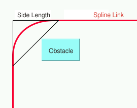
Spline routing
When the layout algorithm needs to create
a bend, the spline routing tries to determine a triangle at the
bend so that the curve of the spline runs inside this triangle.
The size of the triangle depends on the available free space and
the location of the other nodes, which are considered obstacles
for the spline. The side length of the triangle is controlled by
two parameters:
layout.setMinSplineCurveSize(min)layout.setMaxSplineCurveSize(max)
The algorithm tries to find a triangle with a side length between
min
and
max
. If a lot of free space is available, it chooses a triangle at
max
size. If no free space is available, it chooses a triangle at
min
size, even if this will cause an overlap of the spline with
neighbor nodes. Therefore it is recommended to set the minimum
spline curve size to a very small value.
The algorithm chooses isosceles triangles
whenever possible, because the shape of a spline link looks more
balanced if the curves run inside isosceles triangles. However,
if there is no available space, then isosceles triangles are
impossible and triangles with different side lengths are chosen.
A threshold determines how small a triangle can be before
nonisosceles triangles are chosen:
layout.setBalanceSplineCurveThreshold(threshold)
A spline link filter is a subclass of
IlvSplineLinkFilter
that determines which links are splines. The base class
IlvSplineLinkFilter
simply tests the method
IlvGraphic.isSpline
. Currently,
IlvSplineLinkImage
,
IlvGeneralLink
and
IlvCompositeLink
return true when certain link parameters are set so that they
behave like splines. You can set your own spline link filter that
is adapted to your
IlvGraphic
data structures if needed. Call:
layout.setSplineLinkFilter(filter);
Memory savings
The computation of a layout on a large graph may require a large
amount of memory. Some layout algorithms optionally use two ways
to store data: one which gives the priority to speed (this is the
default case), the other which consumes less memory and is
usually slower. The amount of memory savings depends, of course,
on the implementation of the subclass of IlvGraphLayout. No matter which option you
choose for memory savings, the resulting layout should be the
same.
Example of memory savings
To enable memory savings:
In CSS
Add to the
GraphLayout
section:
memorySavings: "true";
In Java
Use the method:
void setMemorySavings(boolean option)
Memory savings is disabled by default.
To indicate whether a subclass of
IlvGraphLayout
supports this mechanism, use the method:
boolean supportsMemorySavings()
The default implementation returns
false
. You can write a subclass to override this method in order to
return
true
to indicate that this mechanism is supported.
Percentage of completion calculation
Some layout algorithms can provide an
estimation of how much of the layout has been completed. This
estimation is made available as a percentage value that is stored
in the graph layout report. When the algorithm starts, the
percentage value is set to 0. The layout algorithm calls the
following method from time to time to increase the percentage
value by steps until it reaches 100:
void increasePercentageComplete(int newPercentage);
The percentage value can be accessed
from the layout report by using the following method:
int percentage = layoutReport.getPercentageComplete();
To see an example of how to read the percentage value during
the running of a layout, see Graph layout event listeners.
To indicate whether a subclass of IlvGraphLayout supports this mechanism,
use the method:
boolean supportsPercentageComplete()
The default implementation returns
false
. A subclass can override this method to return
true
to indicate that this mechanism is supported.
Preserve fixed links
Sometimes, you want some links of the
graph to be “pinned” (that is, to stay in their current shape
when the layout is performed). You want a way to indicate the
links that the layout algorithm cannot reshape. It makes sense
especially when using a semiautomatic layout (the method where
the user fine-tunes the layout by hand after the layout is
completed) or when using an incremental layout (the method where
the graph, the shape of the links, or both are modified after the
layout has been performed, and then the layout is performed
again).
Example of fixing links
To specify that a link is fixed:
In CSS
- Create a rule that selects the link, for instance:
#link1 { Fixed: "true"; } - Add this CSS statement to the
GraphLayoutsection:preserveFixedLinks: "true";
In Java
Use the method:
void setFixed(Object link, boolean fixed)
If the
fixed
parameter is set to
true
, it means that the link is fixed. To obtain the current
setting for a link:
boolean isFixed(Object link)
The default value is
false
.
To remove the fixed attribute from all
links in the grapher, use the method:
void unfixAllLinks()
The fixed attributes on links are
considered only if you additionally call the following
statement:
layout.setPreserveFixedLinks(true);
To indicate whether a subclass of
IlvGraphLayout
supports this mechanism, use the method:
boolean supportsPreserveFixedLinks()
The default implementation returns
false
. A subclass can override this method to return
true
to indicate that this mechanism is supported.
Preserve fixed nodes
At times, you might want some nodes of the
graph to be “pinned” (that is, to stay in their current position
when the layout is performed). You need a way to indicate the
nodes that the layout algorithm cannot move. It makes sense
especially when using a semiautomatic layout (the method where
the user fine-tunes the layout by hand after the layout is
completed) or when using an incremental layout (the method where
the graph, the position of the nodes, or both are modified after
the layout has been performed, and then the layout is performed
again).
Example of fixing nodes
To specify that a node is fixed:
In CSS
- Create a rule that selects the node, for instance:
#node1 { Fixed: "true"; } - Add this CSS statement to the
GraphLayoutsection:preserveFixedNodes: "true";
In Java
Use the method:
void setFixed(Object node, boolean fixed)
If the
fixed
parameter is set to
true
, it means that the node is fixed. To obtain the current
setting for a node:
boolean isFixed(Object node)
The default value is
false
.
To remove the fixed attribute from all
nodes in the grapher, use the method:
void unfixAllNodes()
The fixed attributes on nodes are
considered only if you also call:
layout.setPreserveFixedNodes(true);
To indicate whether a subclass of
IlvGraphLayout
supports this mechanism, use the method:
boolean supportsPreserveFixedNodes()
The default implementation returns
false
. A subclass can override this method to return
true
to indicate that this mechanism is supported.
Random generator seed value
Some layout algorithms use random numbers (or randomly chosen
parameters) for which they accept a user-defined seed value. For example, the Random Layout
uses the random generator to compute the coordinates of the
nodes. The Uniform Length Edges Layout uses the random generator
to compute some internal variables.
Subclasses of IlvGraphLayout that are designed to
support this mechanism allow the user to choose one of three
ways of initializing the random generator:
- With a default value that is always the same.
- With a user-defined seed value that can be changed when re-performing the layout.
- With an arbitrary seed value, which is different each time. In this case, the random generator is initialized based on the system time.
The user chooses the initialization option
depending on what happens when the layout algorithm is performed
again on the same graph. If the same seed value is used, the same
layout is produced, which may be the desired result. In other
situations, the user may want to produce different layouts in
order to select the best one. This can be achieved by performing
the layout several times using different seed values.
Example of random generator seed value
To specify the seed value:
In CSS
You can specify for instance the seed value 25 of the random
generator by adding the following statements to the
GraphLayout
section:
seedValueForRandomeGenerator: "15";
useSeedValueForRandomGenerator: "true";
The first statement defines the seed
value, and the second statement specifies that the seed value
must be used.
In Java
This example shows how this parameter can be used in Java in
combination with the
java.util.Random
class in your implementation of the method
IlvGraphLayout.layout()
:
Random random = (isUseSeedValueForRandomGenerator()) ?
  new Random(getSeedValueForRandomGenerator()) :
  new Random();
To specify the seed value in Java, use
the method:
void setSeedValueForRandomGenerator(long seed)
The default seed value is
0
.
The user-defined seed value is used
only if you call additionally
layout.setUseSeedValueForRandomGenerator(true);
To indicate whether a subclass of
IlvGraphLayout
supports this parameter, use the method:
boolean supportsRandomGenerator()
The default implementation returns
false
. A subclass can override this method in order to return
true
to indicate that this parameter is supported.
Save parameters to named properties
There are many ways to store your graph
and your parameters:
- The diagram component uses XML files for the data and CSS files for the rendering parameters.
- The diagram component can also use a database.
- The Rogue Wave JViews grapher can be stored in
.ivlfiles.
The base class IlvGraphLayout provides support for saving
the layout parameters (such as
isAnimate
or
isMemorySavings
) to
.ivl
files or to transfer the parameters to named properties. This is
an advanced mechanism that is explained in detail in Saving layout parameters and preferred
layouts. If you use XML files, CSS files, or databases, there is
no point using this advanced mechanism.
To indicate whether a subclass of
IlvGraphLayout
supports this mechanism, use the method:
boolean supportsSaveParametersToNamedProperties()
The default implementation returns
false
. You can write a subclass to override this method in order to
return
true
to indicate that this mechanism is supported.
Stop immediately
Several layout algorithms can stop
computation when an external event occurs, for instance when the
user presses a “Stop” button.
In Java
To stop the layout, you can call:
boolean stopImmediately();
This method is typically called in a multithreaded application
from a separate thread that is not the layout thread. The
method returns
true
if the stop was initiated and
false
if the algorithm cannot stop. The method returns immediately,
but the layout thread usually needs some additional time after
initiating the stop to clean up data structures.
The following code fragment illustrates
the usage.
You start the layout in a separate
thread:
Thread layoutThread = new Thread(new GraphLayoutPerformer(layout, grapher));
layoutThread.start();
The class
GraphLayoutPerformer
is an implementation of the interface
Runnable
that performs layout. The following code is a sketch of this
class:
class GraphLayoutPerformer implements Runnable
{
  ...
  public void run()
  {
    // from now we are busy
    busy = true;
    try {
      // perform the layout
      layout.performLayout(true, true);
    }
    catch (IlvGraphLayoutException e) {
      ... // handle the exception
    }
    finally {
      // we are not busy anymore
      busy = false;
    }
  }
}
The Stop button operates outside the layout thread and simply
calls the method
stopImmediately
of the running layout instance:
Button stopButton = new Button("Stop Layout");
stopButton.addActionListener(new ActionListener() {
    public void actionPerformed(ActionEvent e) {
        if (busy) layout.stopImmediately();
    }
});
Note
A detail has been omitted from the previous code fragment. A
multitasking operation requires that the layout thread calls
the
yield()
or
sleep(t)
methods from time to time. A good place to do this is by using
a graph layout event listener. Event listeners are explained
in Using event listeners.
The consequences of stopping a layout
process depend on the specific layout algorithm. Some layout
algorithms have an iterative nature. Stopping the iteration
process results in a slight loss of quality in the drawing, but
the layout can still be considered valid. Other layout algorithms
have a sequential nature. Interrupting the sequence of the layout
steps might not result in a valid layout. Usually, these
algorithms return to the situation before the start of the layout
process.
To indicate whether a subclass of
IlvGraphLayout
supports this mechanism, use the method:
boolean supportsStopImmediately()
The default implementation returns
false
. You can write a subclass to override this method in order to
return
true
to indicate that this mechanism is supported.
Use default parameters
All the generic parameters have a default
value. After modifying parameters, you may want the layout
algorithm to use the default values. Later, you may want to
return to your customized values. Rogue Wave JViews keeps the
previous settings when you select the default values mode. In
Java, you can switch between the default values mode and the mode
for your own settings using the method:
void setUseDefaultParameters(boolean option)
To obtain the current value:
boolean isUseDefaultParameters()
The default value is
false
. This means that any setting you make will be taken into
consideration and the parameters that have not been specified
will have their default values.