The SDM engine controls the data-to-graphics mapping.
There are four key elements in the data-to-graphics
mapping process:
- A data model that interfaces to the data to display or edit. This data model is completely independent of the GUI, and refers only to the business objects of your application.
- Renderers that style the diagram as a whole and the graphic objects in it.
- A grapher in which the graphic objects representing the data model are created.
- Interactors that permit user actions on graphic objects.
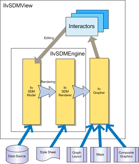
SDM data-to-graphics mapping
As shown in the above figure, the mapping between the
data model and the graphical representation is bidirectional:
- Data model to graphics: the rendering process is controlled by the style sheet, which lets you tell the SDM engine how you want each particular kind of data object to be displayed in the grapher. The rendering process is performed by specialized renderers.
- When the data model is loaded, the SDM engine explores it and creates graphic objects representing the nodes and links defined by the data model in the grapher.
- When the state of an object in the data model changes, the SDM engine updates the graphic object representing the modified data object. The object state may change due to an external application event or after a direct edit of an object property by the user.
- Graphics to data model: the editing process relies on built-in editing facilities that act directly on the underlying data model. The actions in an editing application are implemented by interactors. For example:
- When the user moves a graphic object (for example, in an editor), the SDM engine updates the geometric properties of the object in the data model.
- When the user expands or collapses a node (for example, in a navigation application), the SDM engine updates the expand/collapse status of the object in the data model.
To access the SDM engine associated with a diagram component,
use the getEngine method. Similarly, to access the SDM view associated
with a diagram component, use the getView method. The following code example shows the use
of these methods.
Getting the SDM engine and the SDM view
IlvSDMEngine engine = diagrammer.getEngine();
IlvSDMView view = diagrammer.getView();
You can also choose not to use the IlvDiagrammer class at all. Instead, you can create an SDM engine
( IlvSDMEngine instance) and an SDM view ( IlvSDMView instance) yourself.