The spacing between the node bounds and the
self-link bends can be specified. If a positive value is specified,
this value is used to define the spacing. If a negative value is
specified, the spacing is calculated automatically. The behavior
with negative values is particularly useful for the square
self-link modes in combination with spline links to form
approximate circle shapes for self-links.
In CSS
Add to the GraphLayout section:
selfLinkSpacing: “10”;
In Java
Use the method:
setSelfLinkSpacing(float spacing);
You can specify the position where the
self-link attaches at the bounding box of the node. If the
self-link mode is a rectangular mode, the attach position can be
specified at both border sides where the self-link attaches. For
example, a self-link at the lower right corner attaches at the
lower border side of the node, which can be specified as
x-component, and at the right border side of the node, which can be
specified as y-component. If the self-link mode is a square mode,
it takes into account only the attach position at one of the two
sides, because the shape must be a square, so the other attach
position is automatically calculated.
For experts: If you specify both an
x-attach position and a y-attach position when the self-link mode
is a square mode, the algorithm always chooses the value that
results in a smaller square size.
The attach position is always specified
relative to the corner where the self-link occurs. The coordinate 0
is exactly at the corner and increasing values move the attach
position farther from the corner. Therefore, the rectangular or
square shape of the self-link grows ever larger with increasing
values. For example, when the self-link is at the lower right
corner, increasing x-components moves the attach position toward
the left, and increasing y-components moves it toward the upper
corner. When the self-link is at the upper left corner, increasing
x-components moves the attach position toward the right, and
increasing y-components moves it toward the lower corner. The
attach position can be specified relative to the current size of
the node; 0 specifies the corner where the self-link occurs and 0.5
specifies the middle of the side where the self-link attaches. The
attach position can be specified as an absolute position. If both
relative and absolute attach positions are specified, the real
attach position is the sum of the two of them.
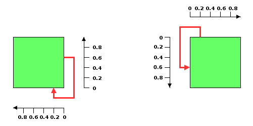
Relative attach position x=0.2, y=0.6
for a self-link at the lower right and upper left corners
In CSS
Add to the GraphLayout section:
layout.selfLinkRelativeAttachPosition: “0.3, 0.5”;
layout.selfLinkAbsoluteAttachPosition: “30, 50”;
In Java
Use the methods:
setSelfLinkRelativeAttachPosition(IlvPoint position);
setSelfLinkAbsoluteAttachPosition(IlvPoint position);