Self-links are links that start and end at the same node. They can
even occur as multiple links, when they are called multiself-link
bundle. When links are routed straight, self-links are not visible,
because they start and end at the same point in the center of the
node. To avoid this effect, the layouts listed in Layout algorithms that are subclasses of
Basic Link Style Layout have a self-link mode that is applied only
when the link style is set to STRAIGHT_LINE_STYLE.
In spite of the name of the link style, the combination of mode and
style causes bends to be added to the self-links to make them
visible. When the link style is NO_RESHAPE_STYLE,
self-link mode has no effect.
Example of specifying how self-links are
routed
In CSS
To specify self-link mode, add to the GraphLayout
section:
selfLinkMode : "NARROW_CONNECTED_SQUARE";
To specify self-link mode, use the method:
void setSelfLinkMode(int mode)
The valid values for mode are given with
the example of Uniform Length Edges layout:
- IlvUniformLengthEdges.NO_BENDS: Self-links are not reshaped with bends and might not be visible.
- IlvUniformLengthEdges.CONNECTED_RECTANGULAR.
- IlvUniformLengthEdges.FREE_RECTANGULAR.
- IlvUniformLengthEdges.CONNECTED_SQUARE.
- IlvUniformLengthEdges.FREE_SQUARE.
- IlvUniformLengthEdges.NARROW_CONNECTED_RECTANGULAR: This mode is the default.
- IlvUniformLengthEdges.NARROW_FREE_RECTANGULAR.
- IlvUniformLengthEdges.NARROW_CONNECTED_SQUARE.
- IlvUniformLengthEdges.NARROW_FREE_SQUARE.
All these modes, except the no-bends mode,
create three bends placed orthogonally, so that the segments
approximately resemble three-quarters of a rectangle or of a
square, the fourth quarter being the node where the self-link is
attached. Depending on the node dimension, the rectangular modes
create four-cornered shapes that are not squares; the square
modes create squares. The square modes are useful for spline
self-links in particular, because the spline can then
approximately resemble three-quarters of a circle.
| Mode | Graphical result |
|---|---|
| CONNECTED_RECTANGULAR mode | 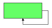
|
| CONNECTED_SQUARE mode | 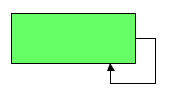
|
| CONNECTED_SQUARE mode with spline link | 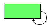
|
The connected modes place the connection
points at the border of the node. The free modes place the bends
at the same position as the corresponding connected modes, but
the link connection point is not enforced; that is, the node and
link are free to select where to place the connection point. The
link segments in the free modes might not be orthogonal, because
the connection point is not enforced.
The free modes are particularly useful when an IlvCenterLinkConnector or IlvPinLinkConnector is used that cannot
change the connection point.
| Mode | Graphical result |
|---|---|
| CONNECTED_SQUARE mode |
|
| FREE_SQUARE mode with link clip connector | 
|
The narrow modes and the other modes
behave the same for single self-links. If you have multiple
self-links at the same node, the self-links are shifted by an
offset to avoid overlaps. In this case, the narrow modes differ
from the other modes; the multiself-link bundle may appear
narrower, because the shift offset of the multiple self-links is
limited by the size of the end node.
| Examples of use of mode and offset | Graphical result |
|---|---|
| CONNECTED_SQUARE mode | 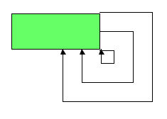
|
| NARROW_CONNECTED_SQUARE mode | 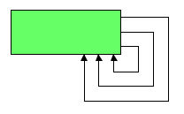
|
Note
When inappropriate link classes or link connector classes are
used, the layout algorithm can raise an IlvInappropriateLinkException if layout is
performed on an IlvGrapher. See Layout exceptions for details and
solutions to this problem.
Self-links can occur at all four corners
of the node. The algorithm determines automatically which corner
is most appropriate, depending on the direction of all other
links. You can restrict which corner should be used.
In CSS
Add to the GraphLayout section:
selfLinkAllowedCorners: "TopLeft BottomLeft TopRight";
The allowed corners must be a space-separated list from TopLeft, BottomLeft,
TopRight, and BottomRight.
If one of these options is not specified, all corners are
allowed.
In Java
Use the method:
setSelfLinkAllowedCorners(int corners);
The allowed corners are a bitwise OR combination chosen from the
following constants; for example, in Uniform Length Edges
layout, IlvUnifiedLengthEdgesLayout.TOP_LEFT,
IlvUnifiedLengthEdgesLayout.BOTTOM_LEFT,
IlvUnifiedLengthEdgesLayout.TOP_RIGHT,
and IlvUnifiedLengthEdgesLayout.BOTTOM_RIGHT.
By default, self-links are oriented
clockwise. You can specify other orientations.
In CSS
Add to the GraphLayout section:
selfLinkOrientation: “COUNTER_CLOCK_WISE”;
In Java
Use the method:
setSelfLinkOrientation(int orientation);
Using IlvUniformLengthEdgesLayout
as an example, the valid values for orientation
are:
- IlvUniformLengthEdgesLayout.CLOCK_WISE
- IlvUniformLengthEdgesLayout.COUNTER_CLOCK_WISE
- IlvUniformLengthEdgesLayout.HORIZONTAL_TO_VERTICALSelf-links start with a horizontal segment and end with a vertical segment.
- IlvUniformLengthEdgesLayout.VERTICAL_TO_HORIZONTALSelf-links start with a vertical segment and end with a horizontal segment.