The following layout parameters work for all
clustering modes.
Link style (CL)
When the layout algorithm moves the nodes, straight-line links, such as instances of
IlvLinkImage, automatically “follow” the
new positions of their end nodes. If the grapher contains other
types of links (for example, IlvPolylineLinkImage or IlvSplineLinkImage), the shape of the
link might not be appropriate because the intermediate points
of the link is not moved. In this case, you can ask the layout
algorithm to automatically remove all the intermediate points
of the links (if any).
Example of specifying automatic removal
of all intermediate points of the links (CL algorithm)
To specify that the layout algorithm
automatically removes all the intermediate points of the links
(if any):
In CSS
Add to the
GraphLayout
section:
linkStyle : "STRAIGHT_LINE_STYLE";
In Java
Use the method:
void setLinkStyle(int style)
The valid values for
style
are:
IlvCircularLayout.NO_RESHAPE_STYLENone of the links is reshaped in any way.IlvCircularLayout.STRAIGHT_LINE_STYLEAll the intermediate points of the links (if any) are removed. It is the default value.
Note
The layout algorithm may raise an IlvInappropriateLinkException if layout
is performed on an IlvGrapher, but inappropriate link
classes or link connector classes are used. See Layout exceptions for details and
solutions to this problem.
Connect links to node center (CL)
This feature is shared by all subclasses of the Basic Link Style
Layout. See Connect links to node center for details.
Multilink and self-link features (CL)
These features are shared by all subclasses of the Basic Link
Style Layout. See Multilink and self-link features for
details.
Using a link clipping interface with the Circular Layout
By default, the Circular Layout does not
place the connection points of links. It relies on the link
connectors of the nodes to determine the connection points. If no
link connectors are installed at the nodes, the default behavior
is to connect to a point at the border of the bounding box of the
nodes.
If the node has a shape other than
rectangular, such as a triangle, rhombus, or circle, you may want
the connection points to be placed exactly on the border of the
shape. This can be achieved by specifying a link clip interface.
The link clip interface allows you to correct the calculated
connection point so that it lies on the border of the shape.
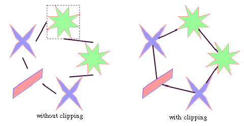
The following figure shows an example of
link clipping.

Effect of link clipping interface
You can modify the position of the connection points of the links
by providing a class that implements the IlvLinkClipInterface. An example for the
implementation of a link clip interface is in Link clipping.
Example of setting a link clip interface
(CL algorithm)
To set a link clip interface:
In Java
Use the method:
void setLinkClipInterface(IlvLinkClipInterface interface)
Note
The link clip interface requires link connectors at the nodes of
an IlvGrapher that allow connector pins to be
placed freely at the node border. It is recommended that you use
IlvFreeLinkConnector or IlvClippingLinkConnector for link
connectors to be used in combination with
IlvGrapher
objects. The clip link connector updates the clipped connection
points automatically during interactive node movements.