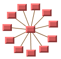
Ring and star topologies are similar in several ways. Look at Ring topology and Star topology to get an idea of their
similarities.

Ring topology

Star topology
Both topologies are composed of nodes drawn
in a circle. For the Circular Layout algorithm, the only difference
between the ring and star topologies is that the star has a special
node, called the star center, that is drawn at the center of the
circle.
Depending on the clustering mode (see Clustering
mode (CL)), the layout allows you to specify the order of the
nodes on the circle (see Cluster membership and order of the nodes in
a cluster (CL)) or it computes the order automatically such that
the number of link crossings is small.
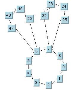
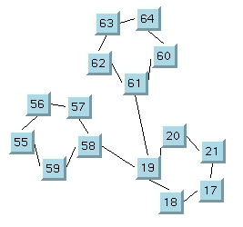
The network topology can be composed of more than one ring or star.
These rings and stars can be partially interconnected; that is, two
or more clusters can have a common node as shown in figure Rings interconnected by common nodes. They
can also be interconnected by links between nodes of two different
clusters as shown in figure Rings interconnected by links.

Rings interconnected by common nodes

Rings interconnected by links
The Circular Layout algorithm lays out ring and star topologies in
a way that preserves the visual identity of each cluster and avoids
overlapping nodes and clusters. See the sample drawings in CL samples.
To understand how layout is performed in the clustering modes
AUTOMATIC
and
BY_CLUSTER_IDS
, consider a graph in which each node represents a ring or star
cluster of a network topology. Add a link between two nodes each
time there is an interconnection between the corresponding
clusters. The Circular Layout algorithm is designed for the case
where the graph obtained in this manner is a tree (that is, a graph
with no cycles). If cycles exist, the layout is performed using a spanning tree of the graph.
Starting from a root cluster (either a ring
or a star), the clusters that are connected to the root cluster are
drawn in a circle that is concentric to the root cluster. The
radius of the circle is computed to avoid overlapping clusters.
Next, the algorithm lays out the clusters connected to these last
clusters on a larger circle, and so on. Each circle is called a
level.
For networks that are not connected (that is, disconnected groups
of clusters exist in the graph), more than one spanning tree
exists. Each spanning tree is laid out separately and placed near
the others. You can see it in the sample drawings in CL samples.
In the clustering mode
BY_SUBGRAPHS
, each subgraph (cluster) keeps its initial position. The subgraphs
can be placed either by a different layout algorithm or
interactively.
Example of CL
In CSS
Below is a sample CSS specification using the Circular Layout
algorithm. Since the Circular Layout places nodes and reshapes
the links, it is usually not necessary to specify an additional
link layout in CSS. The CSS specification can be loaded as a
style file into an application that uses the IlvDiagrammer class (see Graph layout in Rogue Wave JViews Diagrammer).
SDM {
    GraphLayout : "true";
    LinkLayout  : "false";
}

GraphLayout {
    graphLayout    : "Circular";
    clusteringMode : "BY_CLUSTER_IDS";
    offset         : "20";
    levelOffset    : "30";
}
When using the clustering mode
BY_CLUSTER_IDS
(see Clustering mode (CL)), you need to specify
the clustering information (see see Cluster membership and order of the nodes
in a cluster (CL)). When using the clustering mode
AUTOMATIC
, you can optionally specify clustering information, but the
algorithm tries to obtain missing cluster information
automatically by analyzing the topology. When using the
clustering mode
BY_SUBGRAPHS
, each cluster must be a subgraph.
In Java
The following code sample uses the IlvCircularLayout class. This code sample
shows how to perform a Circular Layout on a grapher directly,
without using a diagram component or any style sheet:
 ...
import ilog.views.*;
import ilog.views.graphlayout.*;
import ilog.views.graphlayout.circular.*;
 ...
IlvGrapher grapher = new IlvGrapher();
IlvManagerView view = new IlvManagerView(grapher);
IlvCircularLayout layout = new IlvCircularLayout();
layout.attach(grapher);

layout.setClusteringMode(IlvCircularLayout.BY_CLUSTER_IDS);

 ... /* Fill in the grapher with nodes and links here */

// create identifier for cluster 0
IlvClusterNumber clusterId = new IlvClusterNumber(0);

// specify the cluster identifier for cluster 0
// Assume there are three nodes: node1, node2, node3
// the ordering of the nodes: node1 -> node2 -> node3
layout.setClusterId(node1, clusterId, 0); // index 0
layout.setClusterId(node2, clusterId, 1); // index 1
layout.setClusterId(node3, clusterId, 2); // index 2

// create identifier for cluster 1
clusterId = new IlvClusterNumber(1);

// specify the cluster identifier for cluster 1
// Assume there are three nodes: node4, node5, node6
// the ordering of the nodes: node4 -> node5 -> node6
layout.setClusterId(node4, clusterId, 1); // index 1
layout.setClusterId(node5, clusterId, 2); // index 2
layout.setClusterId(node6, clusterId, 0); // index 0

try {
        IlvGraphLayoutReport layoutReport = layout.performLayout();

        int code = layoutReport.getCode();

        System.out.println("Layout completed (" +
          layoutReport.codeToString(code) + ")");
}
catch (IlvGraphLayoutException e) {
        System.err.println(e.getMessage());
}