After performing the layout on a graph, you
may want to improve the quality of the layout by making some manual
refinements. The subsequent sections describe several ways to
refine your layouts. When the layout is performed again after the
refinements have been applied, only the Nodes placement step of TML
is redone. The results of the Topological Optimization are reused.
This is an important benefit of TML because the algorithm can
recompute a layout using new parameters very quickly, without
performing the time-consuming Topological Optimization step again.
Using fixed nodes (TML)
One reason for applying manual refinements is to avoid
overlapping nodes. To do this, you can use the fixed nodes
mechanism. (See Preserve fixed nodes.)
Take a look at the original layout shown in The original layout with TML. Several
overlapping nodes exist in the original layout because the nodes
are concentrated in a small region and do not use the available
space inside the outer cycle.
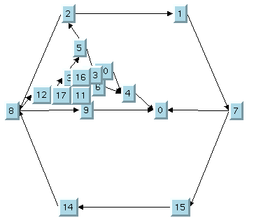
The original layout with TML
To correct the problem, you can perform
the following steps:
- Move nodes 0, 9, and 10 to a place in the free space inside the outer cycle by hand as shown in The TML with some nodes moved .
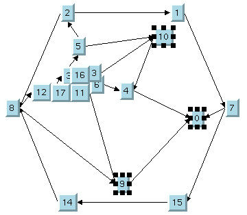 The TML with some nodes moved
 - Specify nodes 0, 9, and 10 as fixed using the setFixed method.
- Use the setPreserveFixedNodes method to specify that the fixed nodes will not be moved when the layout is performed.
- Perform the layout again. Only Step 2 will be performed.The fixed nodes “attract” the other nodes, which are distributed in the larger area inside the outer cycle as shown in The final TML with some fixed nodes.
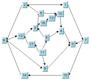 The final TML with some fixed nodes
Using the outer cycle parameter (TML)
By default, the Nodes Placement step of TML produces a layout
using the longest outer cycle computed in the Topological
Optimization step. (The length of a cycle is the number of nodes
that compose the cycle.) Sometimes, a better layout can be
obtained using a different choice of the outer cycle. This
process of changing the outer cycle parameter and performing the
layout again (see Outer cycle (TML)a) is a manual refinement
procedure that can also be used to avoid overlapping nodes.
Note that performing the layout with a new
outer cycle requires very little CPU time.
Using the layout region parameter (TML)
Often, overlapping nodes can be avoided by simply increasing the
size of the layout region (see Layout region (TML)). Layout with small layout region and
overlapping nodes shows a graph drawing where several nodes
overlap because the layout region is too small for the graph. Layout with larger layout region and no
overlapping nodes shows the same graph after increasing the size
of the layout region. As you can see, now there are no
overlapping nodes.
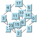
Layout with small layout region and
overlapping nodes
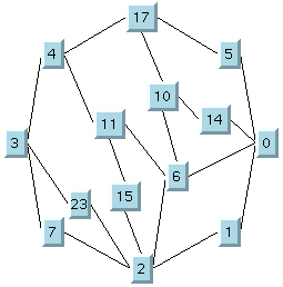
Layout with larger layout region and
no overlapping nodes