Hierarchical Layout (HL)
Describes the Hierarchical Layout algorithm.

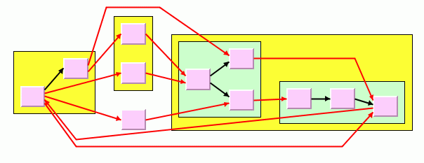
Gives samples of the Hierarchical layout (HL) and explains where it is used.
Lists the features and limitations of the Hierarchical Layout (HL).
Gives an explanation of the Hierarchical Layout (HL) algorithm and a sample.
Lists the generic features and parameters of the Hierarchical Layout (HL).
Describes the parameters specific to the Hierarchical Layout.
Describes how to apply hierarchical layouts sequentially to the same graph.
Describes the constraints on the relative positions of nodes available with the Hierarchical Layout (HL).
Describes how to specify constraints in CSS in a style sheet.
Describes how to specify constraints.
Explains how modes are partitioned into levels and how to set constraints at a specific level.
Describes how to force a node to a particular level with the level index parameter constraint.
Describes how to force several nodes to be at the same level.
Describes how to force a group of nodes to be at the same level.
Describes how to force a node into a higher level than another node.
Describes how to use the position index parameter.
Describes how to use relative position constraints.
Describes how to use side-by-side constraints.
Describes how to use extremity constraints.
Describes how to use swimlane constraints.
Gives a summary of how to specify constraints.
Discusses constraint priorities.
Discusses how validation is done during layout and how to force it if necessary.
Describes when a CSS file can be used.
Describes how to specify level and position indexes or retrieve calculated indexes.
Explains the recursive mode supported by the hierarchical layout.
General information about the HL
HL samples
Describes the
Hierarchical Layout algorithm (class
IlvHierarchicalLayout from the package
ilog.views.graphlayout.hierarchical).
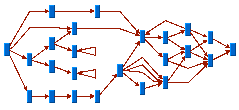
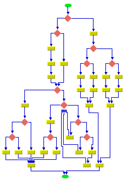
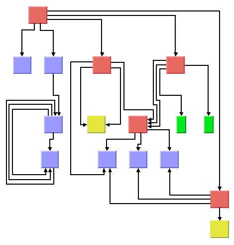
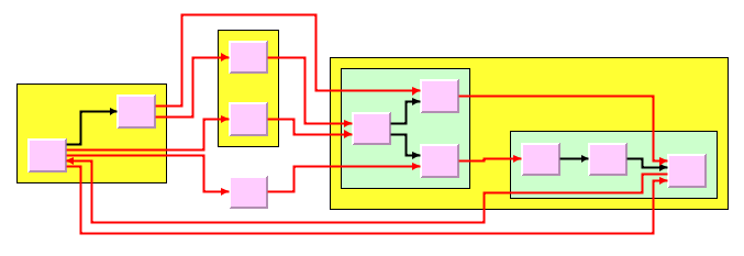
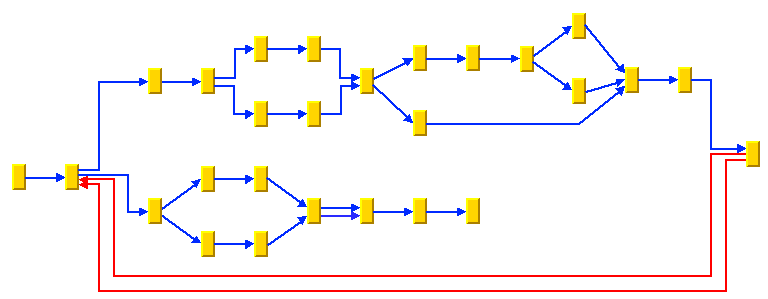
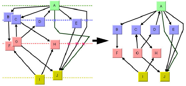
The following sample drawings are produced with the Hierarchical Layout:
Sample layout with self-loops, multiple links, and cycles
Flowchart with orthogonal link style
Sample layout with ports and orthogonal link style
Sample layout of nested graph in recursive layout mode
What types of graphs suit the HL?
Any type of graph, as follows:
Application domains for the HL
Application domains for the Hierarchical Layout include:
Electrical engineering (logic diagrams, circuit block diagrams)
Industrial engineering (industrial process diagrams, schematic design diagrams)
Business processing (workflow diagrams, process flow diagrams, PERT charts)
Software management/software (re-)engineering (UML diagrams, flowcharts, data inspector diagrams, call graphs)
Database and knowledge engineering (database query graphs)
CASE tools (designs diagrams)
Features and limitations of the HL
Features
Organizes nodes without overlaps in horizontal or vertical levels.
Arranges the graph such that most of the links are short and flow uniformly in the same direction (from left to right, from top to bottom, and so on).
Reduces the number of link crossings. Most of the time, produces drawings with no crossings or only few crossings.
Often produces balanced drawings that emphasize the symmetries in the graph.
Supports
self-links (that is, links with the same origin and destination node),
multiple links between the same pair of nodes, and cycles.
Efficient, scalable algorithm. Produces a nice layout for most sparse and medium-dense graphs relatively quickly, even if the number of nodes is large.
Provides several alignment and offset options.
Supports port specifications where links attach the nodes. Allows you to specify which side of a node (top, bottom, left, right) a link can be connected to or to specify which relative port position must be used for the connection.
Supports layout constraints. Allows you to specify relative positional constraints, for instance, that a node is above another node or left of another node.
Incremental and nonincremental mode. In incremental mode, the previous position of nodes are taken into account. Positions the nodes without changing the relative order of the nodes so that the layout is stable on incremental changes of the graph.
Can handle flat and nested graphs. In recursive layout mode, it routes the intergraph links of nested graphs and places the labels of nodes and links in subgraphs.
The computation time depends on the number of nodes, the number of levels, and the number of links that cross several levels. Most of the time, the links are placed between adjacent levels, which keeps the computation time small.
Limitations
The algorithm tries to minimize the number of
link crossings (which is generally an
NP-complete problem). It is mathematically impossible to solve this problem quickly for any graph size. Therefore, the algorithm uses a fast heuristic that obtains a good layout, but not always with the theoretical minimum number of link crossings.
The algorithm tries to place the nodes such that all links point uniformly in the same direction. It is impossible to place cycles of links in this way. For this reason, it sometimes produces a graph where few links are reversed to point into the opposite direction. The algorithm tries to minimize the number of reversed links (which, again, is an NP-complete problem). Therefore, the algorithm uses a fast heuristic resulting in a good layout, but not always with the theoretical minimum number of reversed links.
The computation time required to obtain an appropriate drawing depends most significantly on the number of bends in the links. Since the algorithm places one bend whenever a link crosses a level, the number of bends can grow relatively quickly if the layout requires many long links that span several levels. Therefore, the layout process can become time-consuming for dense graphs (the number of links is relatively high compared to the number of nodes) or for graphs that require many node levels.
The HL algorithm
A brief description of the HL algorithm
This algorithm works in four steps:
Step 1: Leveling
The nodes are partitioned into groups. Each group of nodes forms a level. The objective is to group the nodes in such a way that the links always point from a level with smaller index to a level with larger index.
Step 2: Crossing reduction
The nodes are sorted within each level. The algorithm tries to keep the number of link crossings small when, for each level, the nodes are placed in this order on a line (see
Level and position indexes). This ordering results in the relative position index of each node within its level.
Step 3: Node positioning
From the level indexes and position indexes, balanced coordinates for the nodes are calculated. For instance, for a layout where the link flow is from top to bottom, the nodes are placed along horizontal lines such that all nodes belonging to the same level have (approximately) the same y-coordinate. The nodes of a level with a smaller index have a smaller y-coordinate than the nodes of a level with a higher index. Within a level, the nodes with a smaller position index have a smaller x-coordinate than the nodes with a higher position index.
Step 4: Link routing
The shapes of the links are calculated such that the links bypass the nodes at the level lines. In many cases, it requires that a bend point is created whenever a link needs to cross a level line. In a top-to-bottom layout, these bend points have the same y-coordinate as the level line they cross. (These bend points also obtain a position index).
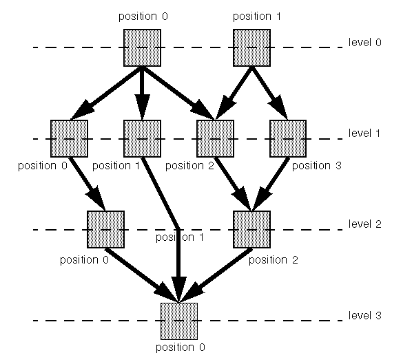
Level and position indexes shows how the Hierarchical Layout algorithm uses the level and position indexes to draw the graph.
Level and position indexes
You can set parameters for the steps of the layout algorithm in several ways. For instance, you can specify the level index that the algorithm must choose for a node in Step 1 or the relative node position within the level in Step 2. You can also specify the justification of the nodes within a level and the style of the link shapes.
Example of HL
In CSS
The following example is a specification that uses the Hierarchical Layout algorithm. Since the Hierarchical Layout places nodes and links, it is usually not necessary to specify an additional link layout in CSS.
The specification can be loaded as a style file into an application that uses the
IlvDiagrammer class (see Graph Layout in Rogue Wave
JViews Diagrammer).
SDM {
GraphLayout : "true";
LinkLayout : "false";
}
GraphLayout {
enabled : "true";
graphLayout : "Hierarchical";
flowDirection : "Bottom";
globalLinkStyle : "POLYLINE_STYLE";
connectorStyle : "CLIPPED_PINS";
horizontalNodeOffset: "20";
verticalNodeOffset : "20";
}
In some situations, a separate link layout renderer may be required:
if the links must be rerouted during interactions, for example, when nodes are moved manually;
if the graph contains nested subgraphs, because the Hierarchical Layout does not handle intergraph links.
In these cases, it is recommended to use the “hierarchical link layout”. The hierarchical link layout is not a separate layout algorithm. It is merely the feature of the link layout renderer to reuse the Hierarchical Layout as a link layout. The following CSS sample specifies the Hierarchical Layout algorithm as node and link layout renderer:
SDM {
GraphLayout : "true";
LinkLayout : "true";
}
GraphLayout {
enabled : "true";
graphLayout : "Hierarchical";
flowDirection : "Bottom";
globalLinkStyle : "ORTHOGONAL_STYLE";
connectorStyle : "EVENLY_SPACED_PINS";
}
LinkLayout {
hierarchical: "true";
}
It is also possible to use the standard link layout (class IlvLinkLayout ) in the link layout renderer (the hierarchical parameter is set to "false" ). However in this case, the link layout determines the shapes of the links. The explanations pertaining to the shape of the links in Hierarchical Layout are valid only if the link layout is disabled.
In Java
In Java™, below is a code sample that uses the
IlvHierarchicalLayout class. This code sample shows how to perform a Hierarchical Layout on a grapher directly without using a diagram component or any style sheet:
...
import ilog.views.*;
import ilog.views.graphlayout.*;
import ilog.views.graphlayout.hierarchical.*;
...
IlvGrapher grapher = new IlvGrapher();
IlvManagerView view = new IlvManagerView(grapher);
... /* Fill in the grapher with nodes and links here */
IlvHierarchicalLayout layout = new IlvHierarchicalLayout();
layout.attach(grapher);
try {
IlvGraphLayoutReport layoutReport = layout.performLayout();
int code = layoutReport.getCode();
System.out.println("Layout completed (" +
layoutReport.codeToString(code) + ")");
}
catch (IlvGraphLayoutException e) {
System.err.println(e.getMessage());
}
Generic features and parameters of the HL
Overview of generic features
The
IlvHierarchicalLayout class supports the following generic features defined in the
IlvGraphLayout class (see
Base class parameters and features):
The following paragraphs describe the particular way in which these parameters are used by this subclass.
Allowed time (HL)
The layout algorithm stops if the allowed time setting has elapsed. (For a description of this layout parameter in the
IlvGraphLayout class, see
Allowed time.) If the layout stops early because the allowed time has elapsed, the nodes and links are not moved from their positions before the layout call and the result code in the layout report is
IlvGraphLayoutReport.STOPPED_AND_INVALID.
Layout of connected components (HL)
The layout algorithm can use the generic mechanism to lay out connected components. (For more information about this mechanism, see
Layout of connected components.) When using this mechanism, each component is laid out in its own individual level structure. Nodes of the first level of one component can be placed at a different position than nodes of the first level of another component.
The generic mechanism to lay out connected components is, however, disabled by default. In this case, the layout algorithm can still handle disconnected graphs. It merges all components into a global level structure.
Link clipping (HL)
The layout algorithm can use a link clip interface to clip the end points of a link. (See
Link clipping.)
This is useful if the nodes have a non-rectangular shape such as a triangle, rhombus, or circle. If no link clip interface is used, the links are normally connected to the bounding boxes of the nodes, not to the border of the node shapes. See
Using a link clipping interface (HL) for details of the link clipping mechanism.
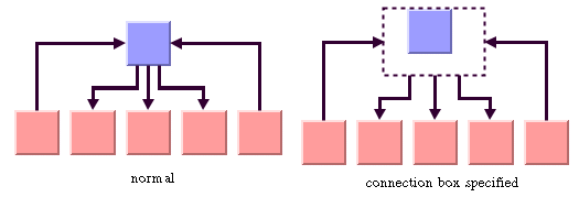
Link connection box (HL)
The layout algorithm can use a link connection box interface (see
Link connection box) in combination with the link clip interface. If no link clip interface is used, the link connection box interface has no effect. For details, see
Using a link connection box interface (HL).
Spline routing (HL)
The layout algorithm supports the generic spline routing mechanism (see
Spline routing). If the style of a link is polyline or orthogonal and the link is a spline, it is routed by the generic spline routing mechanism when it is enabled.
Percentage of completion calculation (HL)
The layout algorithm calculates the estimated percentage of completion. This value can be obtained from the layout report during the run of the layout. (For a detailed description of this features, see
Percentage of completion calculation and
Graph layout event listeners.)
Preserve fixed links (HL)
The layout algorithm does not reshape the links that are specified as fixed. In fact, fixed links are ignored. (For more information about link parameters in the
IlvGraphLayout class, see
Preserve fixed links and
Link style (TL).)
Preserve fixed nodes (HL)
The layout algorithm does not move the nodes that are specified as fixed. (For more information about node parameters in the
IlvGraphLayout class, see
Preserve fixed nodes.) Moreover, the layout algorithm ignores fixed nodes and also does not route the links that are incident to the fixed nodes. It can result in unwanted overlapping nodes and link crossings. However, this feature is useful for individual, disconnected components that can be laid out independently.
Save parameters to named properties (HL)
The layout algorithm is able to save its layout parameters into named properties. This can be used to save layout parameters to
.ivl files. (For a detailed description of this feature, see
Save parameters to named properties and
Saving layout parameters and preferred layouts).
Stop immediately (HL)
The layout algorithm stops after cleanup if the method
stopImmediately is called. (For a description of this method in the
IlvGraphLayout class, see
Stop immediately.) If the layout stops early because the allowed time has elapsed, the nodes and links are not moved from their positions before the layout call and the result code in the layout report is
IlvGraphLayoutReport.STOPPED_AND_INVALID.
Specific parameters of the HL
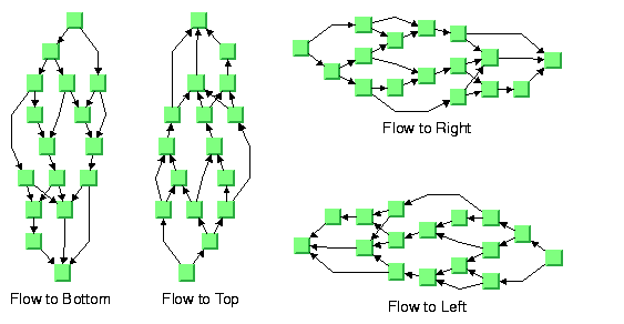
Flow direction (HL)
The flow direction parameter specifies the direction in which most of the links must point. If the flow direction is to the top or to the bottom, the node levels are oriented horizontally and the links mostly vertically. If the flow direction is to the left or to the right, the node levels are oriented vertically and the links mostly horizontally.
If the flow direction is to the bottom, the nodes of the level with index 0 are placed at the top border of the drawing. The nodes with level index 0 are usually the root nodes of the drawing (that is, the nodes without incoming links). If the flow direction is to the top, the nodes with level index 0 are placed at the bottom border of the drawing. If the flow direction is to the right, the nodes are placed at the left border of the drawing.
Flow directions
To specify the flow direction towards the bottom:
In CSS
Add to the GraphLayout section:
flowDirection: "Bottom";
In Java
In Java, use the method:
void setFlowDirection(int direction)
The valid values for the flow direction are:
IlvDirection.Right (the default)
IlvDirection.Left IlvDirection.Bottom IlvDirection.Top In CSS, you omit the prefix IlvDirection when specifying the value of the flow direction.
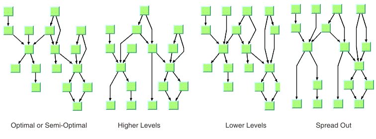
Leveling strategy (HL)
The layout algorithm partitions the nodes into levels (see
A brief description of the HL algorithm). The leveling strategy specifies how the levels are calculated. Besides the leveling strategy, layout constraints (see
Layout constraints for HL), level indexes (see
For experts: more indexes (HL)) as well as the incremental mode (see
Incremental mode with HL) also affect the way the levels are calculated. If the incremental mode is disabled, the leveling strategy determines the levels of all nodes that are not subject to layout constraints and level index specifications.
Leveling strategies
To specify the leveling strategy:
In CSS
Add to the GraphLayout section:
levelingStrategy: "OPTIMAL";
In Java
In Java™, use the method:
void setLevelingStrategy(int strategy)
The valid values for the leveling strategy are:
IlvHierarchicalLayout.SEMI_OPTIMAL (the default)
This value produces often the same result as the optimal strategy, but it is quicker. The layout algorithm uses a heuristic to minimize the sum of level distances for all edges. It pulls root nodes to the highest-numbered possible level and leaf nodes to the lowest-numbered possible level.
IlvHierarchicalLayout.OPTIMAL This value uses an algorithm that minimizes the sum of level distances for all edges. The optimal strategy is slower than the other strategies, but often produces the best result.
IlvHierarchicalLayout.HIGHER_LEVELS Nodes have a tendency to use the possible level with the highest level number. All leaf nodes are at the highest-numbered level. All root nodes are pulled to high-numbered levels as much as possible.
IlvHierarchicalLayout.LOWER_LEVELS Nodes have a tendency to use the possible level with the lowest level number. All root nodes are at level 0. All leaf nodes are pulled to low-numbered levels as much as possible.
IlvHierarchicalLayout.SPREAD_OUT This strategy is a combination of the lower-level and higher-level strategies. All root nodes are at level 0. All leaf nodes are at the highest-numbered level. All inner nodes are at balanced positions.
In CSS, you omit the prefix IlvHierarchicalLayout when specifying the value of the leveling strategy.
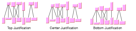
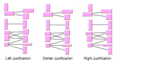
Level justification (HL)
If the layout uses horizontal levels, the nodes of the same level are placed approximately at the same y-coordinate. The nodes can be justified, depending on whether the top border, the bottom border, or the center of all nodes of the same level have the same y-coordinate.
If the layout uses vertical levels, the nodes of the same level are placed approximately at the same x-coordinate. The nodes can be justified to be aligned at the left border, at the right border, or at the center of the nodes that belong to the same level.
To specify the level justification towards the top:
In CSS
Add to the GraphLayout section:
levelJustification: "Top";
In Java
Use the method:
void setLevelJustification(int justification)
If the flow direction is to the top or to the bottom, the valid values for the level justification are:
IlvDirection.Top IlvDirection.Bottom IlvDirection.Center (the default)
Level justification for horizontal levels
If the flow direction is to the left or to the right, the valid values for the level justification are:
IlvDirection.Left IlvDirection.Right IlvDirection.Center (the default)
In CSS, you omit the prefix IlvDirection when specifying the value of the flow direction.
Level justification for vertical levels
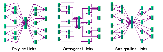
Link style (HL)
The layout algorithm positions the nodes and routes the links. To avoid overlapping nodes and links, it creates bend points for the shapes of links. The link style parameter controls the position and number of bend points. The link style can be set globally, in which case all links have the same shape, or locally on each link such that different link shapes occur in the same drawing.
Link styles
Link style and link shapes
Link styles work only when you use links that can be reshaped. Subclasses of
IlvPolylineLinkImage or of
IlvSplineLinkImage, (e.g.,
IlvGeneralLink ) can be reshaped. Furthermore, link styles work only if free link connectors are installed. Free link connectors are subclasses of
IlvFreeLinkConnector. If you use a diagram component, the free link connectors are automatically installed when needed unless specified differently. If you call layout on an
IlvGrapher directly in Java, the layout algorithm may raise an
IlvInappropriateLinkException if links are neither a subclass of
IlvPolylineLinkImage nor of
IlvSplineLinkImage, or if connectors are not a subclass of
IlvFreeLinkConnector. In this case, you can use the methods
EnsureAppropriateLinkTypes,
EnsureAppropriateLinkConnectors or
EnsureAppropriateLinks defined in the class
IlvGraphLayoutUtil to replace inappropriate links or link connectors automatically, either before layout or when the
IlvInappropriateLinkException is caught. For details on these methods, see the
Java API Reference Manual.For details on the graph model, see
Using the graph model.
Global link style
To set the global link style:
In CSS
Add to the GraphLayout section:
globalLinkStyle: "POLYLINE_STYLE";
In Java
Use the method:
void setGlobalLinkStyle(int style)
The valid values for the link style are:
IlvHierarchicalLayout.POLYLINE_STYLE All links get a polyline shape. A polyline shape consists of a sequence of line segments that are connected at bend points. The line segments can be turned into any direction. This value is the default value.
IlvHierarchicalLayout.ORTHOGONAL_STYLE All links get an orthogonal shape. An orthogonal shape consists of orthogonal line segments that are connected at bend points. An orthogonal shape is a polyline shape where the segments can be turned only in directions of 0, 90, 180 or 270 degrees.
IlvHierarchicalLayout.STRAIGHT_LINE_STYLE All links get a
straight-line shape. All intermediate bend points (if any) are removed. This value often causes overlapping nodes and links.
IlvHierarchicalLayout.NO_RESHAPE_STYLE None of the links is reshaped in any manner. Note, however, that unlike fixed links, the links are not ignored completely. They are still used to calculate the leveling.
IlvHierarchicalLayout.MIXED_STYLE Each link can have a different link style. The style of each individual link can be set such that different link shapes can occur in the same graph.
In CSS, you omit the prefix IlvHierarchicalLayout when specifying the value of the link style.
Individual link style
All links have the same style of shape unless the global link style is MIXED_STYLE. Only when the global link style is MIXED_STYLE can each link have an individual link style.
Different link styles mixed in the same drawing
To specify the style of an individual link:
In CSS
First set the global link style to MIXED-STYLE, then specify a rule that selects the link, for instance:
GraphLayout {
globalLinkStyle: "MIXED_STYLE";
}
#link1
{
LinkStyle: "ORTHOGONAL_STYLE";
}
In Java
Use the methods:
void setLinkStyle(Object link, int style)
int getLinkStyle(Object link)
In this case, the link argument must be a graphic link (subclass of IlvLinkImage ).
The valid values for the link style of local links are the same as for the global link style:
IlvHierarchicalLayout.POLYLINE_STYLE IlvHierarchicalLayout.ORTHOGONAL_STYLE IlvHierarchicalLayout.STRAIGHT_LINE_STYLE IlvHierarchicalLayout.NO_RESHAPE_STYLE Connector style (HL)
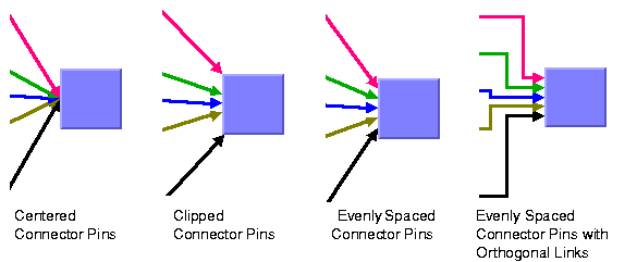
The layout algorithm positions the end points of links (the connector pins) at the nodes automatically. The connector style parameter specifies how these end points are calculated.
Connector styles
To specify the connector style:
In CSS
Add to the GraphLayout section:
connectorStyle: "CLIPPED_PINS";
In Java
Use the method:
void setConnectorStyle(int style)
The valid values for style are:
IlvHierarchicalLayout.CENTERED_PINS The end points of the links are placed in the center of the border where the links are attached. This option is well-suited for polyline links and
straight-line links. It is less suited for orthogonal links, because orthogonal links can look ambiguous in this style.
IlvHierarchicalLayout.CLIPPED_PINS Each link pointing to the center of the node is clipped at the node border. The connector pins are placed at the points on the border where the links are clipped. This option is well-suited for polyline links without port specifications. It must not be used if a port side for any link is specified.
IlvHierarchicalLayout.EVENLY_SPACED_PINS The connector pins are evenly distributed along the node border. This style guarantees that the end points of the links do not overlap. It is the best style for orthogonal links and works well for other link styles.
IlvHierarchicalLayout.AUTOMATIC_PINS The connector style is selected automatically depending on the link style. If any of the links has an orthogonal style or if any of the links has a port side specification, the algorithm chooses evenly spaced connectors. If all the links are straight, it chooses centered connectors. Otherwise, it chooses clipped connectors.
In CSS, you omit the prefix IlvHierarchicalLayout when specifying the value of the connector style.
NOTE The connector style parameter requires link connectors at the nodes of an
IlvGrapher that allow connector pins to be placed freely at the node border. It is recommended that you use
IlvFreeLinkConnector for link connectors to be used in combination with
IlvGrapher objects. If you use a diagram component, the free link connectors are automatically installed when needed, unless specified differently.
End point mode (HL)
Normally, the layout algorithm is free to choose the termination points of each link. However, if fixed-link connectors are used (for instance,
IlvPinLinkConnector), the user can specify that the current fixed termination pin of a link must be used.
The layout algorithm provides two end point modes. You can set the end point mode globally, in which case all end points have the same mode, or locally on each link, in which case different end point modes occur in the same drawing.
Global end point mode
To set the global end point mode:
In CSS
Add to the GraphLayout section:
globalOriginPointMode: "FIXED_MODE";
globalDestinationPointMode: "FIXED_MODE";
In Java
Use the methods:
void setGlobalOriginPointMode(int mode);
void setGlobalDestinationPointMode(int mode);
The valid values for mode are:
IlvLinkLayout.FREE_MODE (the default)
The layout is free to choose the appropriate position of the connection point on the origin/destination node.
IlvLinkLayout.FIXED_MODE The layout must keep the current position of the connection point on the origin/destination node.
IlvLinkLayout.MIXED_MODE Each link can have a different end point mode.
In CSS, you omit the prefix IlvHierarchicalLayout when specifying the value of the end point mode.
The connection points are automatically considered as fixed if they are connected to grapher pins.
Individual end point mode
All links have the same end point mode unless the global end point mode is IlvLinkLayout.MIXED_MODE. Only when the global end point mode is set to MIXED_MODE can each link have an individual end point mode.
To set the end point mode of an individual link:
In CSS
First set the global point modes to MIXED_MODE, then specify a rule that selects the link, for instance:
LinkLayout {
globalOriginPointMode : "MIXED_MODE";
globalDestinationPointMode : "MIXED_MODE";
}
#link1
{
OriginPointMode : "FIXED_MODE";
DestinationPointMode : "FIXED_MODE";
}
In Java
Use the methods:
void setOriginPointMode(Object link, int mode);
int getOriginPointMode(Object link);
void setDestinationPointMode(Object link, int mode);
int getDestinationPointMode(Object link);
The valid values for mode are:
IlvLinkLayout.FREE_MODE (the default)
IlvLinkLayout.FIXED_MODE The connection points are automatically considered as fixed if they are connected to grapher pins.
Using a link connection box interface (HL)
By default, the connector style determines how the connection points of the links are distributed on the border of the bounding box of the nodes, symmetrically with respect to the middle of each side. Sometimes it can be necessary to place the connection points on a rectangle smaller or larger than the bounding box. For instance, it can happen when labels are displayed below or above nodes.
You can modify the position of the connection points of the links by providing a class that implements the
IlvLinkConnectionBoxInterface. An example for the implementation of a link connection box interface is in
Link connection box. To set a link connection box interface in Java, use the method:
The link connection box interface provides each node with a link connection box and tangential shift offsets. The Hierarchical Layout uses the link connection box but does not use the tangential offsets.
The following figure illustrates the effects of customizing the connection box. On the left is the result without any connection box interface. The picture on the right shows the effect if the connection box interface returns the dashed rectangle for the blue node.
Effect of connection box interface
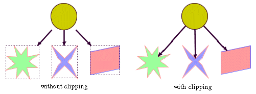
Using a link clipping interface (HL)
By default, the Hierarchical Layout places the connection points of links at the border of the bounding box of the nodes. If the node has a non-rectangular shape such as a triangle, rhombus, or circle, you may want the connection points to be placed exactly on the border of the shape. This can be achieved by specifying a link clip interface. The link clip interface allows you to correct the calculated connection point so that it lies on the border of the shape. The following figure shows an example.
Effect of link clipping interface
You can modify the position of the connection points of the links by providing a class that implements the
IlvLinkClipInterface. An example for the implementation of a link clip interface is in
Link clipping. To set a link clip interface in Java, use the method:
void setLinkClipInterface(IlvLinkClipInterface interface)
NOTE Additionally to the link clip interface, the
IlvClippingLinkConnector can be used. This special link connector updates the clipped connection points automatically during interactive node movements.
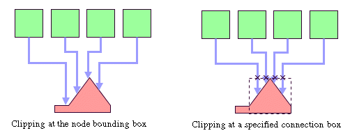
The connector style, the link connection box interface, and the link clip interface work together in the following way: by respecting the connector style, the proposed connection points are calculated on the rectangle obtained from the link connection box interface (or on the bounding box of the node, if no link connection box interface was specified). Then, the proposed connection point is passed to the link clip interface and the returned connection points are used to connect the link to the node.
The following figure shows an example of the combined effect.
Combined effect of link clipping interface and link connection box
If the links are clipped at the red node in previous figure (left), they appear unsymmetrical with respect to the node shape, because the relevant part of the node (here: the triangle) is not in the center of the bounding box of the node, but the proposed connection points are calculated with respect to the bounding box. This can be corrected by using a link connection box interface to explicitly specify a smaller connection box for the relevant part of the node (previous figure, right) such that the proposed connection points are placed symmetrically around the apex of the triangle of the node.
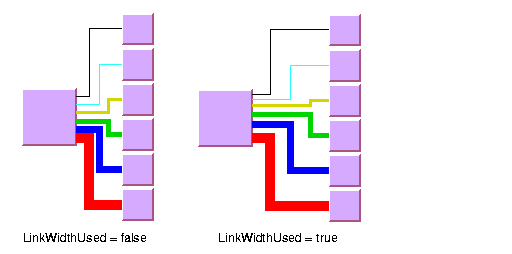
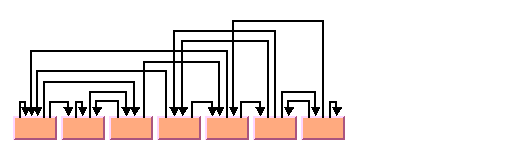
For experts: thick links (HL)
If evenly spaced pins are used as connector style, the links can be evenly spaced with respect to the link center or with respect to the link border. The difference is only visible when links that connect to the same node have different widths. For instance, when the link width indicates the cost or capacity of a flow in the application, many different link widths can occur.
Figure
Using the link width shows the effect of using different link widths. In the drawing on the left, the center of the links are evenly distributed at the left node. Each link has the same space available at the node side. Therefore, the thick links appear closer to each other than do the thinner links and the offsets between the link borders are different. In the drawing on the right, the thick links have more space available than do the thinner links. The offset between the link border (at the segments that connect to the left node) is constant because the link width is considered in the calculation of the connection points.
Using the link width
To enable the connector calculation to respect the link width:
In CSS
Add to the GraphLayout section for instance the statement:
linkWidthUsed: "true";
In Java
Call:
layout.setLinkWidthUsed(true);
The link width setting is disabled by default. The link width has no effect if the connector styles CENTERED_PINS or CLIPPED_PINS are used.
Port sides parameter (HL)
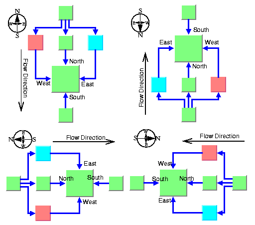
The Hierarchical Layout algorithm produces a layout where most of the link flows are in the same direction. If the flow direction is toward the bottom, usually the incoming links are connected to the top side of the node and the outgoing links are connected to the bottom side of the node. It is also possible to specify on which side a link connects to the node.
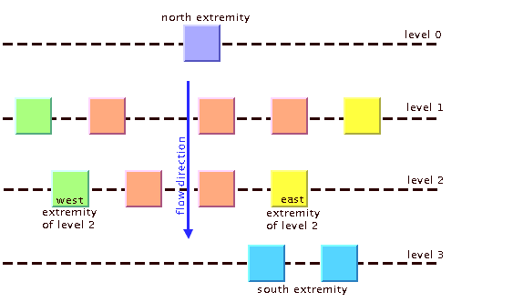
To simplify the explanations of port sides, port sides are referred to by the compass directions north, south, east, and west. The specified link flow direction is always toward south and the first level is toward north. If the flow direction is toward the bottom, north is at the top, south at the bottom, east on the right, and west on the left side of the drawing. If the flow direction is toward right, north is on the left, south on the right, east at the top, and west at the bottom.
The figure
Link connections to port sides shows a drawing where the links connect to the larger middle node at the specified port sides. A compass icon shows the compass directions in these drawings.
Link connections to port sides
You can set at which side the link connects to its source node.
To set at which side the link connects to its source node:
In CSS
Specify a rule that selects the link, for instance:
#link1 {
FromPortSide: "NORTH";
}
In Java
Use the method:
void setFromPortSide(Object link, int side);
In a similar way, you can set at which side the link connects to its destination node.
To set at which side the link connects to its destination node:
In CSS
Specify a rule that selects the link, for instance:
#link1 {
ToPortSide: "SOUTH";
}
In Java
Use the method:
void setToPortSide(Object link, int side);
The valid values for side are:
IlvHierarchicalLayout.UNSPECIFIED (the default)
IlvHierarchicalLayout.NORTH IlvHierarchicalLayout.SOUTH IlvHierarchicalLayout.EAST IlvHierarchicalLayout.WEST In CSS, you omit the prefix IlvHierarchicalLayout when specifying the value of the port side.
To retrieve the current choice for a link, use the methods:
int getFromPortSide(Object link);
int getToPortSide(Object link);
The port sides east and west work well with the orthogonal link style. Polyline links with these port sides sometimes have unnecessary bends. Furthermore, if port sides are specified, the connector style CLIPPED_PINS must not be used.
Port index parameter (HL)
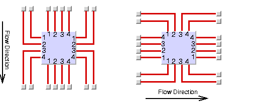
Instead of asking the layout algorithm to decide at which point a link connects to the node border, you can specify where the links connect to the node. You cannot specify the exact location, but you can specify the relative location compared to the connection points of the other links. You can do so by using a port index. Figure
Sample layout with ports and orthogonal link style shows a sample layout with ports at many nodes.
Links that have the same port index connect at the same point of the node. The ports are evenly distributed at the node sides, in a similar way as with the connector style EVENLY_SPACED_PINS. The ports are ordered according to their indexes. On the north and south side of a node, the port indexes increase toward the east. On the east and west sides of a node, the port indexes increase toward the south. By using port indexes in this way, it is easier to rotate a graph by simply changing the flow direction without updating all the port specifications.
Figure
Port index numbering conventions in relation to flow direction shows how the port indexes depend on the flow direction.
Port index numbering conventions in relation to flow direction
Port numbers are normally used in combination with port sides. Therefore, you must specify how many ports are available on each side of a node.
To specify the number of ports:
In CSS
Write a rule that selects the node, for instance:
node.tag1 {
EastNumberOfPorts: "4";
WestNumberOfPorts: "4";
NorthNumberOfPorts: "4";
SouthNumberOfPorts: "4";
}
Alternatively, you can write:
node.tag1 {
NumberOfPorts: "EAST,4";
NumberOfPorts: "WEST,4";
NumberOfPorts: "NORTH,4";
NumberOfPorts: "SOUTH,4";
}
Both are equivalent.
In Java
Use the method:
void setNumberOfPorts(Object node, int side, int numberOfPorts);
For example, to use four ports on each side of a specific node, use the calls:
layout.setNumberOfPorts(node, IlvHierarchicalLayout.EAST, 4);
layout.setNumberOfPorts(node, IlvHierarchicalLayout.WEST, 4);
layout.setNumberOfPorts(node, IlvHierarchicalLayout.NORTH, 4);
layout.setNumberOfPorts(node, IlvHierarchicalLayout.SOUTH, 4);
The node side is specified again by EAST, WEST, NORTH, and SOUTH. To retrieve the retrieve the number of ports available at the node, use the method:
int getNumberOfPorts(Object node, int side);
After the number of ports per side is specified, you can choose which port each link connects to.
To choose the port side and the port index for a link:
In CSS
Specify a rule that selects the link, for instance:
link.tag1 {
FromPortSide: "NORTH";
FromPortIndex: "3";
ToPortSide: "SOUTH";
ToPortIndex: "3";
}
In Java
To specify the connection at the source node, use the methods:
void setFromPortSide(Object link, int portSide);
void setFromPortIndex(Object link, int portIndex);
To specify the connection at the destination node, use the methods:
void setToPortSide(Object link, int portSide);
void setToPortIndex(Object link, int portIndex);
To obtain the current port index of a link, use the methods:
int getFromPortIndex(Object link);
int getToPortIndex(Object link);
Using the port side and port index specifications are additional constraints for the layout algorithm. The more constraints are specified, the more difficult it is to calculate a layout. Therefore, if too many links have a specified port index, this resulting layout might have more link crossings and be less balanced.
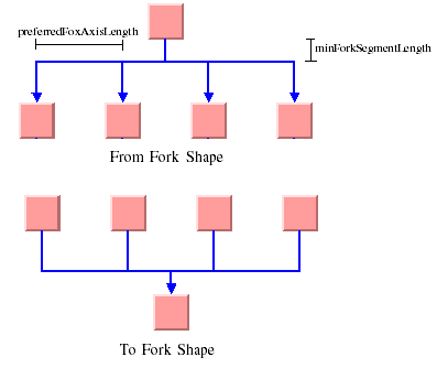
Fork link shapes (HL)
If several links start at the same position and are orthogonally routed, it is sometimes preferred that the links share the first two link segments. The shape of a link bundle of this kind looks like a fork. To enable the fork shape mode for outgoing links, call:
layout.setFromFork(true);
To enable the fork shape mode for incoming links:
In CSS
Add to the GraphLayout section:
fromFork: "true";
toFort: "true";
In Java
Call:
layout.setToFork(true);
These statements are effective only if the links are routed orthogonally. The fork appears only at those links that start or end exactly at the same point. Specifying
setFromFork(true) by itself does not force the links to start at the same point. To force links to start or end at the same point, use the center connector style (see
Connector style (HL)) or specify the same port for the links (see
Port index parameter (HL)).
Fork link shapes
There are two spacing parameters for the fork shape:
In CSS
Add to the GraphLayout section:
minForkSegmentLength: "30.0";
preferredForkAxisLength: "10.0";
In Java
void setMinForkSegmentLength(float length)
Sets the minimum length of the segment that is directly near the node.
void setPreferredForkAxisLength(float length)
Sets the preferred length of the fork axis per branch (the second segment next to the node).
If the fork has five branches, the entire axis has the preferred length five times the specified parameter. The preferred fork axis length is only a hint for the layout algorithm. If enough space is available, the algorithm enlarges the fork axis to avoid unnecessary link bends. If there is not enough space, the algorithm can calculate a fork axis that is smaller than the preferred one.
Fork link shapes can sometimes look ambiguous, in particular when a link starts at the same point where another link ends. In this case, it is impossible to recognize whether the arrowhead belongs to one or the other link.
Link priority parameter (HL)
The layout algorithm tries to place the nodes such that all links are short, point in the flow direction, and do not cross each other. However, it is not always possible. Often, links cannot have the same length. If the graph has
cycles, some links must be reversed against the flow direction. If the graph is a
nonplanar graph, some links have to cross each other.
The link priority parameter controls which links must be selected if long, reversed, or crossing links are necessary. Links with a low priority are more likely to be selected than links with a high priority. It does not mean that low-priority links are always longer, reversed, or crossed. The graph can have a structure such that no long, reversed, or crossing links are necessary.
To set the link priority:
In CSS
Specify a rule that selects the link, for instance:
link.tag1 {
LinkPriority: "2.0";
}
In Java
Use the methods.
void setLinkPriority(Object link, float priority)
float getLinkPriority(Object link)
The default value of the link priority is 1.0. Negative link priorities are not allowed.
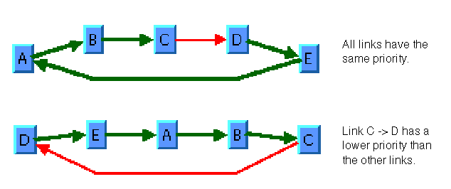
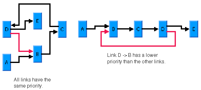
For an example of using the link priority, consider a cycle A->B->C->D->E->A. It is impossible to lay out this graph without reversing any link. Therefore, the layout algorithm selects one link to be reversed. To control which link is selected, you can give one link a lower priority than the others. This link is then reversed. In figure
Working with link priorities, the bottom layout shows the use of the link priority. The link C->D was given the priority 0.5, while all the other links have the priority 1.0. Therefore C-D is reversed. The top layout in
Working with link priorities shows what happens when all links have the same priority. Link E->A is reversed.
Working with link priorities
The use of link priorities is important in combination with ports. Links with “from” ports on the south side and “to” ports on the north side are preferably laid out opposite to the flow direction. Such a feedback link can cause parts of the drawing to tip over. The figure
Using link priorities and ports shows an example. The red link is a feedback link with port specifications. To obtain the correct result as shown in the right side of the following figure, you would set the priority of the feedback link to a very low value.
Using link priorities and ports
Spacing parameters (HL)
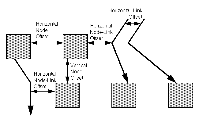
The spacing of the layout is controlled by three kinds of spacing parameters: the minimum offset between nodes, the minimum offset between parallel segments of links, and the minimum offset between a node border and a bend point of a link or a link segment that is parallel to this border. The offset between parallel segments of links is at the same time the offset between bend points of links. All three kinds of parameter occur in both directions: horizontally and vertically.
Spacing parameters
To set the spacing parameters:
In CSS
Add to the GraphLayout section:
horizontalNodeOffset: "30.0";
horizontalLinkOffset: "15.0";
horizontalNodeLinkOffset: "20.0";
verticalNodeOffset: "30.0";
verticalLinkOffset: "15.0";
verticalNodeLinkOffset: "20.0";
In Java
For the horizontal direction, use the methods:
void setHorizontalNodeOffset(float offset)
void setHorizontalLinkOffset(float offset)
void setHorizontalNodeLinkOffset(float offset)
For the vertical direction, use the methods:
void setVerticalNodeOffset(float offset)
void setVerticalLinkOffset(float offset)
void setVerticalNodeLinkOffset(float offset)
For a layout with horizontal levels (the flow direction is to the top or to the bottom), the horizontal node offset is the minimum distance between nodes of the same level. The vertical node offset is the minimum distance between nodes of different levels, that is, the minimum distance between the levels. For non-orthogonal link styles, the horizontal link offset is basically the minimum distance between bend points of links. The horizontal node-link offset is the minimum distance between the node border and the bend point of a link. For horizontal levels, the vertical link offset and the vertical node-link offset play a role only if the link shapes are orthogonal.
Similarly, for a layout with vertical levels (the flow direction is to the left or to the right), the vertical node offset controls node distances within the levels. The horizontal node offset is the minimum distance between the levels. In this case, the vertical link offset and the vertical node-link offset always play a role, while the horizontal link offset and the horizontal node-link offset impact the layout only with orthogonal links.
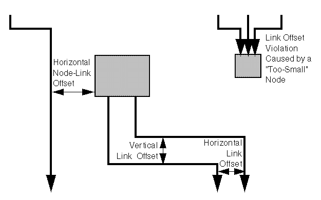
For orthogonal links, the horizontal link offset is the minimum distance between parallel, vertical link segments. The vertical link offset is the minimum distance between parallel, horizontal link segments. However, the layout algorithm cannot always satisfy these offset requirements. If a node is tiny but has many incident links, it can be impossible to place the links orthogonally with the specified minimum link distance on the node border. In this case, the algorithm places some link segments closer than the specified link offset.
Spacing parameters for orthogonal links
Incremental mode with HL
In some circumstances you, might need to use a sequence of layouts on the same graph. For example:
You work with graphs that have become out-of-date and you need to extend the graph. If you perform a layout on the extended graph, you probably want to identify the parts that were already laid out in the original graph. The layout should not change very much when compared with the layout of the original graph.
The first layout results in a drawing with minor deficiencies. You want to solve these deficiencies manually and perform a second layout to clean up the drawing. The second layout probably should not greatly change the parts of the graph that were already acceptable after the first layout.
The Hierarchical Layout normally works non-incrementally. It performs a layout from scratch and moves all nodes to new positions and reroutes all links. The previous positions of nodes have no influence on the result of the layout. Hence, even a small change can cause a large effect on the next layout.
But the Hierarchical Layout also supports incremental sequences of layout that “do not change very much.” It can place the nodes close to their previous positions, so that you can more easily identify the parts that had already been laid out in the original graph. Incremental mode takes the previous positions of the nodes into account. In this mode, the algorithm preserves the relative order of the levels and the nodes within the levels in the subsequent layout. It does not preserve the absolute positions of the nodes, but it tries to detect the structure of the previous layout by examining the node coordinates. For instance, if two nodes are in the same level, then they stay in the same level after an incremental layout. If a node is in a higher level than another node, it stays in the higher level.
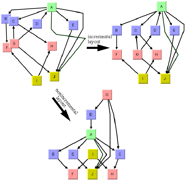
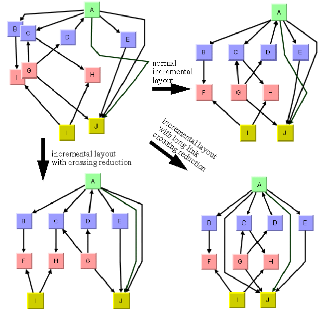
The following figure illustrates the difference between an incremental and nonincremental layout.
Incremental and nonincremental layouts
Incremental mode is disabled by default.
To enable incremental mode:
In CSS
Add to the GraphLayout section:
incrementalMode: "true";
In Java™
layout.setIncrementalMode(true);
Important Be aware of the difference between the incremental mode of the Hierarchical Layout and the incremental layout flag of the SDM Graph Layout Renderer.
Important The CSS statement incrementalMode: "true";
Important controls the incremental mode of Hierarchical Layout and specifies that all layouts are performed incrementally.
Important This feature of the Hierarchical Layout is described in the subsequent sections.
Important Conversely, the CSS statement
Important incrementalLayout: "true";s
Important controls the Node Layout Renderer and means that the Node Layout Renderer switches between incremental mode and nonincremental mode depending on whether an object is selected or not.
Important This advanced feature of the Node Layout Renderer is explained in
The GraphLayout renderer in
Developing with the JViews Diagrammer SDK. Phases of the incremental mode
The layout algorithm analyzes the drawing in incremental mode in the following way:
1. First, it determines from the node coordinates which nodes must belong to the same level. For instance, if the flow direction is towards the bottom, it tries to detect horizontal reference lines at those vertical positions where many nodes are placed along a line. The specified vertical node offset helps to detect these lines because the horizontal reference lines must be approximately the vertical node offset apart. See the following figure.
2. All nodes that touch the same reference line are assigned to the same level.
3. It determines the order of the nodes within each level by analyzing where the node touches the reference line. For instance, if the flow direction is towards the bottom, it determines from the x coordinate of the nodes how they are ordered within the levels.
4. If long links span several levels, the algorithm can preserve the shape of a long link. It determines the point where a link crosses the level reference line. It creates a bend point for the long link inside the level. It tries to preserve the order of the bend points in each level. For instance, if in a flow direction towards the bottom, a long link bypasses another node on the right side, then the incremental layout tries to find a similar shape of the link that bypasses the node on the right side. See the following figure.
5. Finally, the layout tries to calculate the absolute positions of the nodes that respect the levels and the ordering within the levels. It tries to balance the node positions. However, it also tries to place each node close to its previous position. Both criteria often compete with each other, because to get a perfect balance, nodes must sometimes move far from their original position. The Hierarchical Layout contains a parametrized heuristic to satisfy both criteria.
The following figure shows the result of the incremental phases.
Incremental layout phases
Expert parameters of the incremental mode
Each phase of the incremental mode can be parameterized. These layout parameters are effective only if incremental mode is enabled.
Minimizing long link crossings
The incremental layout tries to preserve the shape of long links that cross several levels. It implies that link crossings between long links are not resolved. If crossings of long links are not wanted, it might be better to reroute long links from scratch. The following figure shows four hierarchy trees, with the original layout at the upper left. The lower right shows the result if long links are rerouted, and the upper right shows the result if the shape of long links is preserved.
Crossing reduction during incremental layouts
To reroute long links from scratch, you must enable the crossing reduction mechanism for long links:
In CSS
longLinkCrossingReductionDuringIncremental: "true";
In Java
layout.setLongLinkCrossingReductionDuringIncremental(true);
The crossing reduction of long links determines only the shape of the links. It does not influence the order of the other nodes within the levels.
Minimizing all link crossings
Optionally, you can apply a crossing reduction to all nodes within each level. In this case, the incremental layout determines from the node coordinates which nodes belong to the same level, but it might reorder the nodes within the levels completely to avoid link crossings. It also reorders the long links in this case. The previous figure, lower left shows the result. Notice that the order of the nodes “F,” “G,” and “H” have changed to resolve the link crossings.
To enable the crossing reduction for all nodes:
In CSS
crossingReductionDuringIncremental: "true";
In Java
layout.setCrossingReductionDuringIncremental(true);
Setting absolute level positioning
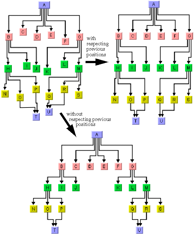
The incremental layout tries to place the nodes in absolute positions that are close to the previous positions. It tries to avoid nodes moving a long distance, because even if the relative order of the nodes within the levels does not change, long distances can be confusing for users. It is much easier to keep a mental map of the diagram if the nodes remain close to the previous positions.
The following figure illustrates node repositioning with and without taking the previous positions into account. The incremental layout of the original graph (upper left) results in the graph at the upper right, which is easier to recognize as being the same graph than is the graph at the bottom.
The absolute level positioning feature is enabled by default, but it can be disabled.
To disable the absolute level positioning feature:
In CSS
Write the statement:
incrementalAbsoluteLevelPositioning: "false";
In Java
Call
layout.setIncrementalAbsoluteLevelPositioning(false);
With this statement, the layout does not try to place the nodes close to the previous positions. It places the nodes such that the layout is balanced. However, to create a perfect balance, the layout might need to move a few nodes so far apart that you no longer recognize the diagram (see the following figure, bottom).
Absolute positioning during incremental layouts
Setting absolute level position range and tendency
If absolute level positioning is enabled, it competes with the aesthetic criteria to create a balanced layout. Because nodes must stay close to their previous positions, the diagram after incremental layout might be unbalanced and unsymmetrical. The Hierarchical Layout algorithm uses a heuristic that you can influence by two parameters, the absolute level position range and tendency.
The absolute level positioning feature is enabled by default, but it can be disabled.
To disable the absolute level positioning feature:
In CSS
Add in the GraphLayout section:
incrementalAbsoluteLevelPositioning: "100";
In Java
Call:
layout.setIncrementalAbsoluteLevelPositionRange(100);
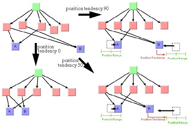
This statement specifies that within the range of 100 coordinate units from the old position of the node, the balance is the only criteria for the placement. This means that a node whose optimal position is less than 100 coordinate units away from its previous position is placed exactly at its optimal position. Nodes whose optimal position is farther away are placed at a position that is a compromise between previous position and optimal position. See the following figure, right.
To set the absolute level position tendency:
In CSS
Add in the GraphLayout section:
incrementalAbsoluteLevelPositionTendency: "70";
In Java
Call:
layout.setIncrementalAbsoluteLevelPositionTendency(70);
This statement specifies that when the optimal position of a node is far away from its previous position, its position is 70% influenced by its previous position and 30% influenced by its optimal position. Imagine a rubber band that tries to pull a node to its previous position, and another rubber band that tries to pull the same node to its optimally balanced position. The level position tendency 70 means that one rubber band pulls with 70% of the force towards the previous position, and the other rubber band pulls with 30% towards the optimal position. Increasing the tendency means that the node stays closer to its old position, decreasing it means that the node moves closer to its optimal position. If you set the tendency to 0%, it has the same effect as disabling the incremental absolute level positioning (see the following figure).
Absolute positioning during incremental layouts
Marking nodes for incremental layout
Incremental layout normally treats all nodes and links of the drawing in the same way. However, you might have added nodes and links to the drawing programmatically, and the new nodes and links do not have meaningful coordinates yet. Perhaps you have placed them all at the origin (0,0), or at random coordinates. In this case, you need an incremental layout that takes into account the coordinates of all nodes that were previously laid out while ignoring the coordinates of the new nodes.
The incremental mode of the Hierarchical Layout allows you to specify in Java which nodes cannot be laid out incrementally by calling the method:
layout.markForIncremental(nodeOrLink);
If you call this statement, the node or link is marked such that its coordinates are ignored during the next incremental layout. The positions of marked nodes and links are calculated from scratch. The mark is valid only until the next layout and is automatically cleared afterward.
Layout constraints for HL
The Hierarchical Layout algorithm supports relative position constraintson nodes. Such a constraint is a rule on how a particular node (or a group of nodes) must be placed with respect to the other nodes. The constraints influence the relative positions. For example, you can force node A to be on the left side of node B, so the position of A is expressed relative to the position of B. It is theoretically possible to specify contradicting constraints: if you specify that node A must be on the left side of B and B must be on the left side of A, then these constraints are not solvable at the same time. If A is on the left side of B, then B must be on the right side of A. The Hierarchical Layout algorithm tries to detect and resolve constraint conflicts automatically. It ignores those constraints that are infeasible. Since the automatic constraint resolution is time consuming, it is recommended to specify nonconflicting constraints when possible.
Constraints must be used only if the incremental mode is disabled. In fact, the incremental mode is implemented with additional constraints that are added internally. Hence, if you use constraints during the incremental mode, it is likely that the system detects so many constraint conflicts that you get unexpected results.
Constraints must be used carefully. The more constraints are specified, the more difficult it is to calculate a layout. Therefore, this resulting layout can have more link crossings and be less balanced than a graph with no constraints.
Each type of constraint is represented by a subclass of IlvHierarchicalConstraint. The following constraint types are available:
IlvLevelRangeConstraint | Forces a node into a range of certain levels |
IlvSameLevelConstraint | Forces two nodes to the same level. |
IlvRelativeLevelConstraint | Forces a node to a lower/higher level than another node. |
IlvGroupSpreadConstraint | Forces a group of nodes on levels that are no more than a specified spread value apart. |
IlvRelativePositionConstraint | Forces a node to a lower/higher position than another node of the same level. |
IlvSideBySideConstraint | Forces two nodes of the same level to be placed side by side. |
IlvExtremityConstraint | Forces a node to the first or last level, or to the first or last position within a level. |
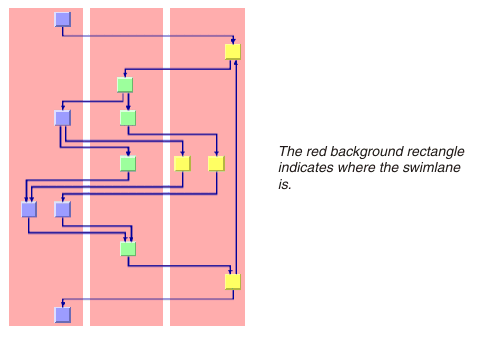
IlvSwimLaneConstraint | Forces a group of nodes into the same rectangular swimlane area. |
Specifying constraints in CSS for HL
There are two ways to specify constraints in a style sheet:
In an external file that contains the constraints
By means of
style rules in the style file directly
When you do not use a diagram component with style sheet capabilities, you can still use constraints.
Writing style rules that specify constraints is very powerful but complex. It is illustrated in section
For experts: specifying constraints in CSS directly (HL). This topic concentrates on specifying constraints in an external file.
In the CSS file, you can write:
GraphLayout {
graphLayout : "Hierarchical";
constraintsURL : "url(Constraints.txt)";
}
This means that the layout constraints are specified in a separate file named Constraints.txt. This file contains the constraint in a very simple format, for example:
SameLevelConstraint {
firstNode: node2
secondNode: node5
}
RelativeLevelConstraint {
lowerSubject: { node5 }
higherSubject: { node9 }
priority: 50.0
}
LevelRangeConstraint {
subject: { node11, node12 }
minLevel: 3
maxLevel: 4
}
The complete example can be found at:
The style files are in the subdirectory data. The example shows how to specify constraints by loading an external file as well as how to specify constraints by writing style rules directly.
Adding and removing constraints for HL
You can add constraints to the Hierarchical Layout in Java™. You allocate a new constraint object and call this method on the IlvHierarchicalLayout instance:
void addConstraint(IlvHierarchicalConstraint constraint);
You can add as many constraints as you want. The constraints are respected during the subsequent layout calls until you remove them. To remove the most recent constraint, call:
void removeConstraint();
To remove a specific constraint, call:
void removeConstraint(IlvHierarchicalConstraint constraint);
To remove all existing constraints, call:
void removeAllConstraints();
You can retrieve the constraints that were added to a Hierarchical Layout with the method:
Enumeration getConstraints()
Node groups
Some constraints affect single nodes. Other constraints affect groups of nodes. The class IlvNodeGroup is a convenient way to specify a group of nodes in Java. You can create a group of nodes in the following way:
group = new IlvNodeGroup();
while (...) {
group.add(node);
}
A node group has a similar functionality to a vector. You can ask for the size and elements of the group, remove elements from the group, or check whether a node already belongs to the group. You can also convert a vector of nodes into a group:
group.add(node) | Adds a node to the group. |
group.remove(node) | Removes a node from the group. |
group.contains(node) | Checks whether a node is in the group. |
group.size() | Returns the number of nodes in the group. |
group.elements() | Returns the nodes of the group as an Enumeration. |
group = new IlvNodeGroup(vector) | Creates a group that contains the nodes stored in the input vector. |
Level range constraints (HL)
In Step 1 of the layout algorithm (the leveling phase), the nodes are partitioned into levels. These levels are indexed starting from 0. For instance, when the flow direction is to the bottom, the nodes of the level index 0 are placed at the topmost horizontal level line and the nodes with larger level index are placed at a position lower than the nodes with smaller level index (see
Level and position indexes). The layout algorithm calculates these level indexes automatically.
You can choose how the levels are partitioned by specifying the range of the level index for some nodes. The nodes are placed in the levels whose index is in the specified range. You have to specify the minimum and maximum index of the level.
To specify the minimum and maximum index of the level:
In CSS
In the constraint file, specify:
LevelRangeConstraint {
subject: { node11 }
minLevel: 5
maxLevel: 7
}
This specification forces the graphic of the model node with ID “node11” to be placed between the minimum level 5 and the maximum level 7, that is, either in level 5, level 6, or level 7.
In Java™
Call:
layout.addConstraint(new IlvLevelRangeConstraint(node, 5, 7));
Notice that in this case, node contains the graphic node (subclass of IlvGraphic ). If you want to place the node exactly at level 5, call:
layout.addConstraint(new IlvLevelRangeConstraint(node, 5, 5));
Alternatively, you can call:
layout.setSpecNodeLevelIndex(node, 5);
which has the same meaning.
If you want to force the node to level 5 and above, set UNSPECIFIED as the maximum level.
In CSS
In the constraint file, specify:
LevelRangeConstraint {
subject: { node11 }
minLevel: 5
maxLevel: UNSPECIFIED
}
In Java
Call:
layout.addConstraint(
new IlvLevelRangeConstraint(node, 5, IlvHierarchicalLayout.UNSPECIFIED));
If you want to force the node to level 5 and below (that is, level 0, ..., 5), set UNSPECIFIED as the minimum level; for example, in Java:
layout.addConstraint(
new IlvLevelRangeConstraint(node, IlvHierarchicalLayout.UNSPECIFIED, 5));
In this particular case, you could also use zero (0) as the minimum level because the level indexes start at 0.
You can apply the constraint to a group of several nodes at once. It has the same effect as specifying the constraint for each single node of the group, but it is more memory efficient and convenient. For instance, if you want to force the group of three nodes to the levels 5 - 7:
To specify these parameters:
In CSS
In the constraint file, specify:
LevelRangeConstraint {
subject: { node11, node12, node13 }
minLevel: 5
maxLevel: 7
}
In Java
Create a
IlvNodeGroup object (see
Node groups) of the three nodes and add it to the constraint in the following way:
layout.addConstraint(new IlvLevelRangeConstraint(nodeGroup, 5, 7));
Level index parameter (HL)
The level index is a special case of a level range constraint (see
Level range constraints (HL)). It forces the node to one particular level. For your convenience, you can specify the level index of a node directly by the method:
void setSpecNodeLevelIndex(Object node, int index)
You pass a single node as the first argument (not a node group). The default index value is -1. If the default value is used, or if a node is set to a negative level index, the level index is considered to be unspecified. In this case the layout algorithm automatically calculates an appropriate level index during the leveling phase of the algorithm.
To obtain the specified level index for a node, use the method:
int getSpecNodeLevelIndex(Object node)
However, this method returns the value that was set by setSpecNodeLevelIndex. If the level index was specified by allocating a corresponding level range constraint that has the same meaning, getSpecNodeLevelIndex still returns -1.
Warning Using arbitrarily large level indexes is not recommended. For instance, if you set the level index of a node to 100000, the layout algorithm creates 100,000 levels even if the graph has far fewer nodes. It causes the layout algorithm to become slow.
Same level constraints (HL)
If you want to force several nodes to the same level with fixed index, you can set the level index parameter of these nodes accordingly (see
Level index parameter (HL)) or use a level range constraint (see
Level range constraints (HL)). However, if you want to force several nodes to the same level
without forcing them to a specific level index, you cannot use these mechanisms. You must use a same level constraint.
To set the same level constraint:
In CSS
In the constraint file, specify:
SameLevelConstraint {
firstNode: node1
secondNode: node2
}
In Java™
Call:
layout.addConstraint(new IlvSameLevelConstraint(node1, node2));
This forces node1 and node2 to be placed in the same level, but it does not constrain them to any particular level.
The following figure illustrates the placement of nodes at the same level.
All nodes fixed at same level
Group spread constraints (HL)
An alternative way to force a group of nodes to be at the same level is by specifying a group spread constraint with a spread size of zero (0). In general, the group spread constraint forces a group of nodes to k+1 subsequent levels. The number k is the spread size. It does not select the lowest or highest level index of the group, but requires only that the nodes are placed no more than k levels apart. Hence, if k=0, all nodes of the group are placed at the same level.
To illustrate the general group spread constraint on nodes with ID “nodeA’, “nodeB” and “nodeC”:
In CSS
In the constraint file, specify:
GroupSpreadConstraint {
group: { nodeA, nodeB, nodeC }
spreadSize: 2
}
In Java™
To use the group spread constraint on graphic nodes (subclasses of
IlvGraphic), call:
IlvNodeGroup nodeGroup = new IlvNodeGroup();
nodeGroup.add(nodeA);
nodeGroup.add(nodeB);
nodeGroup.add(nodeC);
layout.addConstraint(new IlvGroupSpreadConstraint(nodeGroup, 2));
The constraint is satisfied if the highest level index for nodeA, nodeB, and nodeC is no more than two levels apart from the smallest level index of the nodes. For instance, the constraint is satisfied if the level indexes for nodeA, nodeB, and nodeC are 1, 2, 3; or if they are 7, 8, 9; or if they are 16, 14, 15. The constraint is also satisfied if all three nodes are placed at level 5, or if two of the nodes are placed at level 15 and the third node at level 13. The constraint is not satisfied if the level indexes for nodeA, nodeB, and nodeC are 3, 5, 6, because in this case the highest index (6) is more than two levels away from the lowest index (3).
Relative level constraints (HL)
If the flow direction is towards the bottom, level 0 is topmost in the drawing. In this layout, you can specify by relative level constraints that a node is above or below another node. If the flow direction is towards the right, level 0 is leftmost in the drawing. Here you can specify by relative level constraints that a node is left or right of another node.
In CSS
In the constraint file, specify:
RelativeLevelConstraint {
lowerSubject: { nodeA }
higherSubject: { nodeB }
priority: 1000.0
}
In Java
In Java™, call:
layout.addConstraint(
new IlvRelativeLevelConstraint(nodeA, nodeB, priority));
This forces nodeA to be placed at a level with a smaller index than nodeB. Since relative level constraints compete with each other, you must specify the priority of the constraint. In fact, links also impose constraints on the system, and the link priority has the same impact as the constraint priority. A link with priority 10 forces its (usually) source node (unless ports are specified) into a lower level than its target node. To force the source node into a higher level than the target node, you need to create a constraint with a higher priority than the link. For instance, to ensure that the constraints are satisfied even if there are many links, you can use link priorities 0 - 10 and constraint priorities 1000 - 10,000.
You can also create a relative level constraint between groups of nodes.
In CSS
In the constraint file, specify a comma-separated list of nodes, such as
lowerSubject: { node1, node2, node3 }
In Java
Call:
layout.addConstraint(
new IlvRelativeLevelConstraint(nodeGroup1, nodeGroup2, priority));
Position index parameter (HL)
In Step 2 of the layout algorithm (the crossing reduction phase), the nodes are ordered within the levels. All nodes that belong to the same level get a position index starting from 0. For instance, when the flow direction is to the bottom, the node with the position index 0 is placed in the leftmost position within its level. The nodes with a larger position index are placed farther to the right than the nodes with a smaller position index in the same level. The nodes of different levels are independent. The node of the first level with the position index 0 is to the left of the node of the first level with the position index 1, but not necessarily to the left of a node of another level with position index 0. Long links crossing a level also obtain a position index (see
Level and position indexes). The layout algorithm calculates these position indexes automatically.
You can affect how the nodes are positioned within each level by specifying the position index of some nodes. The nodes are placed at the specified position within their level.
To specify the position index of a node in Java™, use the method:
void setSpecNodePositionIndex(Object node, int index)
The default value is -1. If the default value is used, if a node is set to a negative position index, or if a node is set to a position index that is larger than the number of nodes of its level, the layout automatically calculates an appropriate position index during the crossing reduction step.
To obtain the current position index of a node, use the method:
int getSpecNodePositionIndex(Object node)
Relative position constraints (HL)
Working with absolute node position indexes is inconvenient in certain situations. For example, if two nodes belong to the same level, you might want to force one node to a position with a lower index than the other node without fixing the absolute positions of the nodes. You can achieve it by using a relative position constraint.
The relative position constraint forces a specific order upon the nodes of a level, but it does not specify which nodes are directly neighbored. For instance, a relative position constraint can force nodeA to be placed somewhere at a lower position than nodeB, but there can be many nodes between nodeA and nodeB.
In CSS
In the constraint file, specify:
RelativePositionConstraint {
lowerSubject: { nodeA }
higherSubject: { nodeB }
priority: 1000.0
}
In Java™
Call:
layout.addConstraint(
new IlvRelativePositionConstraint(nodeA, nodeB, priority));
This forces nodeA to a lower position than nodeB. If the flow direction is towards the bottom, the nodes are in horizontal levels; hence the constraint means that nodeA is placed at the left side of nodeB. If the flow direction is towards the right, the nodes are in vertical levels; hence the constraint means that nodeA is placed below nodeB.
The relative position constraint has an effect only if both nodes actually belong to the same level. To achieve it, you can, for instance, use a same level constraint in addition. There is no way to influence the relative position of nodes that belong to different levels.
Similar to the relative level constraint, the relative position constraint can be applied to node groups. These constraints also have priorities that indicate which constraints dominate if a constraint conflict occurs. The higher the priority, the more likely the constraint is satisfied when resolving constraint conflicts.
Side-by-side constraints (HL)
To force nodes to be directly neighbored, use the side-by-side constraint.
In CSS
In the constraint file, specify:
SideBySideConstraint {
group: { nodeA, nodeB, nodeC }
priority: 100.0
}
In Java™
You can create a side-by-side constraint on a group of type
IlvNodeGroup (see
Node groups):
layout.addConstraint(
new IlvSideBySideConstraint(nodeGroup, priority));
If the node group consists of just two nodes, it forces the two nodes to be placed side by side. However, it does not specify which node is at the lower node position and which node is at the higher node position. If the group consists of more than two nodes, it forces the nodes to be placed at consecutive positions such that all nodes are clustered together. A node that does not belong to the group cannot be placed between the nodes of the group.
For example, assume that the group contains the three nodes A, B, C. The constraint is satisfied if the position indexes of A, B, and C are 3, 4, 5 or 9, 7, 8. However, if node D is placed between A and B (say, D has position 4, A has position 3, and C has position 5), then the constraint is not satisfied because D does not belong to the same group.
The side-by-side constraint has an effect only if the nodes actually belong to the same level. To achieve it, you can, for instance, use a same level constraint in addition.
Side-by-side constraints have priorities that decide how to resolve constraint conflicts. The higher the priority, the more likely the constraint is satisfied.
You can use side-by-side constraints to create nested clusters. For example, in Java:
IlvNodeGroup group1 = new IlvNodeGroup();
group1.add(nodeA);
group1.add(nodeB);
group1.add(nodeC);
group1.add(nodeD);
layout.addConstraint(
new IlvSideBySideConstraint(group1, 10.0f));
IlvNodeGroup group2 = new IlvNodeGroup();
group2.add(nodeB);
group2.add(nodeC);
layout.addConstraint(
new IlvSideBySideConstraint(group2, 10.0f));
The first constraint specifies that nodeA, nodeB, nodeC, and nodeD must be clustered. The second constraint specifies that nodeB and nodeC are clustered inside the larger cluster. This means that no other node can be placed between the four nodes and, furthermore, nodeA or nodeD cannot be placed between nodeB and nodeC. The following figure shows four solutions that satisfy both constraints.
Sketch of solutions for side-by-side constraints
Extremity constraints (HL)
To force a node to the first level, you can specify:
layout.setSpecNodeLevelIndex(node, 0);
However, you cannot specify a level index for the last level because it is unknown at the beginning of layout how many levels are created. It is unwise to specify:
layout.setSpecNodeLevelIndex(node, java.lang.Integer.MAX_VALUE);
because it creates many empty levels between the levels used and the last one. Even though these empty levels are removed in postprocessing steps, it influences the speed and quality of the layout. (In fact, the algorithm runs out of memory if you set the specified level index unreasonably high.)
By using constraints you can achieve the same effect more efficiently.
To force a node to the first level:
In CSS
In the constraint file, specify:
ExtremityConstraint {
node: node
side: NORTH
}
In Java
In Java™, call:
layout.addConstraint(
new IlvExtremityConstraint(node, IlvHierarchicalLayout.NORTH));
To force a node to the last level:
In CSS
In the constraint file, specify:
ExtremityConstraint {
node: node
side: SOUTH
}
In Java
Call:
layout.addConstraint(
new IlvExtremityConstraint(node, IlvHierarchicalLayout.SOUTH));
With compass directions as a convenient reference (see
Port sides parameter (HL)), the first level indicates the north pole and the last level indicates the south pole. You can also specify extremity constraints for the east and west sides:
layout.addConstraint(
new IlvExtremityConstraint (node1, IlvHierarchicalLayout.EAST));
layout.addConstraint(
new IlvExtremityConstraint (node2, IlvHierarchicalLayout.WEST));
The west extremity constraint forces the node to the lowest position index within its level, and the east extremity constraint forces the node to the highest position index within its level. The position indexes specify the relative position within the level. For instance, a node with west extremity constraint is the leftmost node within its level, if the flow direction is towards the bottom. However, it does not affect other levels; there can be a node in another level that is still placed farther to the left.
The following figure illustrates some extremity constraints.
Sketch of Extremity Constraints
Swimlane constraints (HL)
Swimlanes are rectangular areas orthogonal to the levels.
If the link flow direction is towards the bottom or top, the levels are horizontal rows and the swimlanes are vertical columns.
If the flow direction is towards the left or right, the levels are vertical columns and the swimlanes are horizontal rows.
You can use swimlanes if the nodes are partitioned into groups, to indicate which nodes belong to a certain group. The nodes in the same swimlane are placed so that it is possible to draw a surrounding rectangle around them. Swimlanes allow you to organize the graph in a table-like manner. For example, you can have a workflow diagram where nodes represent actions; the swimlanes could then represent the departments that perform these actions. Each node can belong to only one swimlane.
To assign a group of nodes to a swimlane:
In CSS
In the constraint file, specify:
SwimLaneConstraint {
group: { node1, node2, node3 }
relativeSize: -1.0
positionIndex: -1
eastMinMargin: 0.0
westMinMargin: 0.0
}
In Java
In Java™, call:
layout.addConstraint(new IlvSwimLaneConstraint(new IlvNodeGroup(nodeVector)));
All nodes of the node vector are placed in the same swimlane rectangle. If a graph has many swimlane rectangles, the relative order of these swimlanes is determined automatically. The size of the swimlane rectangle depends on the nodes that belong to the swimlane. However, you can specify the relative order, relative size, and the margins of the swimlane as well by using the constructor:
public IlvSwimLaneConstraint(IlvNodeGroup group,
float relativeSize,
int positionIndex,
float westMinMargin,
float eastMinMargin)
Swimlanes
The relative size indicates how large this swimlane is compared to the other swimlanes. Assume that the flow direction is towards the bottom. In this case, the relative size indicates the width of the swimlane. All swimlanes with the same relative size have the same width. A swimlane with a relative size that is twice the value of another swimlane will have twice the width of the other swimlane. The actual number of this parameter does not matter, only how large the value is compared to the other swimlanes. If you do not want to restrict the size of the swimlane, set the value to 0. In this case, the width of the swimlane is independent of the other swimlanes.
The minimum margin is the margin of the swimlane in absolute coordinates. If the flow direction is towards the bottom, then the west minimum margin is the minimum horizontal distance between the leftmost node of the swimlane and the left swimlane border, and the east minimum margin is the minimum horizontal distance between the rightmost node of the swimlane and the right swimlane border.
The position index indicates the order of the swimlanes. Just as nodes have position indexes, the swimlanes are placed sequentially at relative positions numbered from 0 to n. In a top-down layout, the swimlane with position 0 is the leftmost swimlane, and the swimlanes with higher position indexes are placed farther to the right. If the swimlanes have the position index -1, the layout algorithm determines the appropriate position automatically.
A swimlane constraint is always evaluated, even if the incremental mode is enabled. The constraint has a higher priority than the relative position constraint and the side-by-side constraint. You can specify side-by-side constraints for a group of nodes that belong to the same swimlane, but side-by-side constraints of nodes of different swimlanes are ignored. You can specify relative position constraints between nodes of the same swimlane. You can also specify relative position constraints between one entire swimlane group and another swimlane group, which effectively orders the swimlanes. But relative position constraints are ignored if they would require breaking the swimlanes apart. The swimlane constraint dominates the specified position indexes and the extremity constraints, that is, if a swimlane constraint is used, you cannot specify position indexes or east/west extremity constraints for any node.
TIP The automatic conflict resolution can handle conflicting constraints. However, to speed up the layout, it is recommended that you specify constraints in such a way that there are no conflicts.
Summary of constraints file as opposed to constraints in Java (HL)
The following summary indicates how to specify constraints:
Applications based on the class
IlvDiagrammer which use style sheets (CSS files) can specify constraints in a constraint file.
Applications that do not use style sheets but work on
IlvGrapher and
IlvHierarchicalLayout instances can add constraints directly to the layout instance in Java™.
In the constraint file, nodes are specified by their model ID (see
getID).
Constraints specified in Java take the graphic nodes (subclasses of
IlvGraphic ) directly as arguments.
Relative level constraints, relative position constraints, level range constraints, group spread constraints, side-by-side constraints, and swimlane constraint can work in node groups. To specify a node group:
In the constraint file, use a comma separated list of node IDs:
{ node1, node2, node3 }
In Java, use the API of the class
IlvNodeGroup:
IlvNodeGroup group1 = new IlvNodeGroup();
group1.add(node1);
group1.add(node2);
group1.add(node3);
Warning Mixing style sheets and constraint specifications in Java is not recommended. In an application that uses style sheets (CSS files), the constraints specified in the CSS file override those created in Java, when the layout is performed.
Constraint priorities (HL)
A set of constraints can cause conflicts. This means that not all of the constraints can be satisfied at the same time. For instance, it is impossible to force two nodes into the same level by an IlvSameLevelConstraint while forcing one of the nodes to a higher level than the other node by an IlvRelativeLevelConstraint. In this case, one of the two constraints must be ignored during layout.
In general, constraint conflicts are resolved by ignoring the constraints with the lowest priority while the constraints with the highest priority get satisfied. The following rules explain the constraint priorities in detail.
The constraints that influence the level into which a node is placed are applied before the constraints that influence the position of the node within a level.
For instance, the extremity constraint with the south side is translated into several same level constraints and several relative level constraints.
They are never in conflict with each other. They dominate all other constraints, even the specified level index.
If two nodes are forced to the same level but have disjoint specified level ranges, then the level range is ignored. In the following example:
layout.addConstraint(new IlvSameLevelConstraint(node1, node2));
layout.setSpecNodeLevelIndex(node1, 5);
layout.setSpecNodeLevelIndex(node2, 10);
both node1 and node2 are placed at level 5. The conflicting specification: layout.setSpecNodeLevelIndex(node2, 10) is ignored.
The
IlvRelativeLevelConstraint is dominated by the same level constraint, by the level range constraint, and by the direct specification of level indexes.
If several relative level constraints conflict with each other, the one with the highest specified priority dominates. However, all links are implicitly considered relative level constraints as well. If links with high priority force a node to a certain level, then a relative level constraint with lower priority is ignored.
The constraint has a higher priority than the relative position constraint and the side-by-side constraint. You can specify side-by-side constraints for a group of nodes that belong to the same swimlane, but side-by-side constraints of nodes of different swimlanes are ignored. You can specify relative position constraints between nodes of the same swimlane. You can also specify relative position constraints between one entire swimlane group and another swimlane group, which effectively orders the swimlanes. But relative position constraints are ignored if they would require breaking the swimlanes apart. The swimlane constraint dominates the specified position indexes and the extremity constraints, that is, if a swimlane constraint is used, you cannot specify position indexes or east/west extremity constraints for any node.
Typically you use a same level constraint to force the nodes to the same level, and then a side-by-side constraint to force the nodes to a certain ordering. The side-by-side constraints dominate the relative position constraints. If several side-by-side constraints are conflicting, the one with the highest specified priority dominates the other constraints.
It is dominated by the side-by-side constraint; however, conflicts with side-by-side constraints are rare. If several relative position constraints are conflicting, the one with the highest specified priority dominates the other constraints.
For experts: constraint validation (HL)
Constraints that you specify can become invalid. For instance, if you add a constraint that node A must be to the left side of node B, but you remove A from the graph, then this constraint becomes invalid. It simply does not make sense any more, even though it does not conflict with any other constraint. The layout instance automatically removes invalid constraints from time to time because they are a waste of memory. The validation check is done during layout. Forcing a validation check is normally not necessary but if you want to do it, call:
layout.validateConstraints();
It removes all invalid constraints from the Hierarchical Layout and cleans up the memory. The constraint validation does not check which constraints have conflicts. The main effect of the validation is that the constraint system uses less memory afterward.
NOTE >> A constraint is valid if it is meaningful. Two valid constraints are conflicting if the system cannot satisfy them both at the same time. Invalid constraints cannot be conflicting because they are meaningless.
Hence, constraint validation and constraint resolution are different phases. Constraint validation performs a quick local test. It removes invalid constraints from the layout instance completely. It does not affect conflicting constraints.
Constraint resolution checks whether a set of valid constraints are in conflict with each other. Thus, constraint resolution is a complex process on a network of multiple related constraints. Constraint resolution decides which constraints can be solved and which cannot. But the constraint resolution does not remove conflicting constraints from the layout instance, it delivers a solution that can ignore some constraints.
For experts: specifying constraints in CSS directly (HL)
SDM applications that use style files (CSS files) can specify an external constraint file that refers to the constrained nodes by their node IDs. Alternatively, it is possible to specify the constraints in the CSS file directly.
The general mechanism for specifying constraints in CSS directly is:
<node selector> {
<constraint property>: "<constraint name>,<additional parameters>";
}
The meaning is that the selected node participates in the constraint with the specified name. The constraint name is an arbitrary string that identifies the constraint. The name is needed because several nodes usually participate in the same constraint; therefore, several such
style rules are required to specify the constraint completely.
For example, to specify a relative-level constraint between the nodes with ID activity1 and participant1, use the following style rules:
#activity1 {
LowerRelativeLevelConstraint: "ConstraintA,5000";
}
#participant1 {
HigherRelativeLevelConstraint: "ConstraintA,5000";
}
The constraint property LowerRelativeLevelConstraing indicates that this rule specifies the lower node of a relative-level constraint. The property HigherRelativeLevelConstraint indicates that this rule specifies the higher node of a relative-level constraint. The constraint name “ ConstraintA ” is used to distinguish this relative-level constraint from other constraints of the same type. The parameter 5000 is the priority of this constraint.
All constraint types can be specified similarly. The constraint name is arbitrary, except for the extremity constraint: Here, only the names “ EAST ”, “ WEST ”, “ NORTH ” and “ SOUTH ” are allowed as constraint names, and they indicate at the same time the side of the constraint.
A sample CSS sheet with various constraint specifications can be found at:
For further details about specifying constraints in Java™, see the class
IlvGraphLayoutRenderer.
The following table lists all constraint properties that are available in CSS.
CSS Constraint properties
Constraint Property | Corresponding Specification in Constraint File |
LevelRangeConstraint | LevelRangeConstraint { subject: {...} } |
FirstSameLevelConstraint | SameLevelConstraint { firstNode: ... } |
SecondSameLevelConstraint | SameLevelConstraint { secondNode: ... } |
GroupSpreadConstraint | GroupSpreadConstraint { group: {...} } |
LowerRelativeLevelConstraint | RelativeLevelConstraint { lowerSubject: {...} } |
HigherRelativeLevelConstraint | RelativeLevelConstraint { higherSubject: {...} } |
LowerRelativePositionConstraint | RelativePositionConstraint { lowerSubject: {...} } |
HigherRelativePositionConstraint | RelativePositionConstraint { higherSubject: {...} } |
SideBySideConstraint | SideBySideConstraint { group: {...} } |
ExtremityConstraint | ExtremityConstraint { node: ... } |
SwimLaneConstraint | SwimLaneConstraint { group: {...} } |
NOTE >> If constraints are specified in the CSS file directly, each node can participate only in one constraint of each type at most. For instance, you can specify an extremity constraint “EAST” for a node, but you cannot specify an extremity constraint “SOUTH” for the same node at the same time. You can however specify another constraint type (e.g. a level range constraint) for the same node at the same time.
This limitation is due to technical reasons pertaining to the mechanism whereby CSS files are processed by the SDM engine. If you specify constraints by an external constraint file, there is no such limitation: for instance., in the external constraint file, you can specify as many extremity constraints for the same node as you want.
For experts: more indexes (HL)
The Hierarchical Layout allows you to specify the level index and the position index of a node.
In CSS
Specify the level and position index of a node with ID “ node1 ” in the following way:
#node1 {
SpecNodeLevelIndex: "5";
SpecNodePositionIndex: "33";
}
In Java™
You specify the level and position index of a graphic node in the following way:
layout.setSpecNodeLevelIndex(node, 5);
layout.setSpecNodePositionIndex(node, 33);
How these indexes are used depends on the graph topology and the additional constraints. For example, the specified level index can be in conflict with some
IlvLevelRangeConstraint or
IlvSameLevelConstraint. In this case, the constraint priorities determine how the conflict is resolved (see
Constraint priorities (HL)). If the incremental mode is enabled, the specified node level and position index are ignored, since the incremental mode tries to preserve old node positions. It is also possible to obtain the indexes of nodes that were calculated during layout.
Calculated level index
The layout algorithm allows you to access the level index that was calculated for a node by a previous layout. Use the method:
int getCalcNodeLevelIndex(Object node)
If the node was never laid out, this method returns -1. Otherwise, it returns the previous level index of the node.
In an application that specifies layout parameters entirely in Java, the method can be used to specify the level index for the next layout in the following way:
int index = layout.getCalcNodeLevelIndex(node);
layout.setSpecNodeLevelIndex(node, index);
It ensures that the node is placed at the same level as in the previous layout.
If the graph is detached from the layout algorithm, the calculated level index of a node is set back to -1.
NOTE >> Be aware of the difference between the methods
getCalcNodeLevelIndex and
getSpecNodeLevelIndex. The first one returns the level index calculated by the previous layout. The second one returns the specified level index, even if there was no previous layout.
For instance, consider two nodes A and B. Node A has no specified level index and node B has a specified level index 5. Before the first layout, the method getCalcNodeLevelIndex returns -1 for both nodes because the levels have not been calculated yet. However, getSpecNodeLevelIndex returns -1 for A and 5 for B. After the first layout, node A can be placed at level 4. Now, getCalcNodeLevelIndex returns 4 for node A and 5 for node B and getSpecNodeLevelIndex still returns -1 for A and 5 for B.
Calculated position index
The layout algorithm allows you to access the position index within a level that was calculated for a node by a previous layout. Use the method:
If the node was never laid out, this method returns -1. Otherwise, it returns the previous position index of the node within its level.
To ensure that the node is placed at the same level at the same relative position as in the previous layout, use the following code in an application that specifies layout parameters entirely in Java:
layout.setSpecNodeLevelIndex(node,
layout.getCalcNodeLevelIndex(node));
This example code works only if the generic connected component layout is disabled and the port sides EAST or WEST are not used in the layout.
If the graph is detached from the layout algorithm, the calculated position index of a node is set back to -1.
NOTE Be aware of the difference between the methods
getCalcNodePositionIndex and
setSpecNodePositionIndex.The first one returns the position index calculated by the previous layout and -1 if there was no previous layout. The second one returns the specified position index even if there was no previous layout. This behavior is similar to the behavior of the specified and calculated level index (see
Calculated level index).
Recursive layout
A graph that is a node in another graph is called a subgraph. Links that connect nodes of different subgraphs are called intergraph links. In
Recursive hierarchical layout on nested graph with polyline link style, all red links are intergraph links and all black links are normal links. This is explained in detail in
Nested layouts.
Hierarchical layout can treat a nested graph at once, placing all nested nodes and routing all links including the intergraph links.
Hierarchical layout can even place the labels in the nested graph.
To enable recursive mode:
In CSS
Add to the GraphLayout section:
recursiveLayoutMode: "true";
In Java
Use this method:
void setRecursiveLayoutMode(boolean enable);
and call performLayout with the third parameter set to true in the following way:
layout.performLayout(force, redraw, true);
Recursive layout mode requires that all subgraphs are laid out in the same style (for example, they must all use the same flow direction). This is automatically the case when calling
layout.performLayout(force, redraw, true) and it is also the case when using CSS without specifying individual graph layouts per subgraph. If different layout styles are needed per subgraph, you must specify an individual layout per subgraph as described in
Individual layout styles per subgraph and in
Advanced recursion: mixing different layouts in a nested graph.
In this case, hierarchical layout cannot route the intergraph links and you must use a Link Layout algorithm to route the intergraph links.
Recursive hierarchical layout on nested graph with polyline link style
Recursive hierarchical layout on nested graph with orthogonal link style
Setting layout parameters in recursive mode
When you use CSS, the layout parameters are specified in CSS as usual, and the SDM engine handles the internal details automatically.
When you want to specify layout parameters in Java™ code, in recursive layout mode, the hierarchical layout is attached to the top-level graph. Global layout parameters must be set on this layout instance. Layout parameters per node or per link must be set in the following way:
// node is directly contained in subgraph
IlvHierarchicalLayout sublayout =
(IlvHierarchicalLayout)topLevelLayout.getRecursiveLayout().getLayout(subgraph);
sublayout.setSpecNodeLevelIndex(node, 5);
This means that layout parameters per node or per link cannot be set on the top-level layout, but on a sublayout retrieved by means of
IlvRecursiveLayout from the top-level layout.
Layout constraints in recursive layout mode work only between nodes that belong to the same subgraph. Constraints among nodes of different subgraphs are ignored. The concepts EAST, WEST, NORTH, SOUTH of extremity constraints are interpreted relative to the subgraph, not relative to the global graph. Similarly to the layout parameters per node or per link, the constraint must be installed at the layout instance of the subgraph of the node.
// node1, node2 is directly contained in subgraph
IlvHierarchicalLayout sublayout =
(IlvHierarchicalLayout)topLevelLayout.getRecursiveLayout().getLayout(subgraph);
sublayout.addConstraint(new IlvSameLevelConstraint(node1, node2));
Swimlane constraints do not work in recursive layout mode at all.
Label layout
If recursive layout mode is enabled, hierarchical layout can also place the node and link labels. This feature is useful, because placing labels after a recursive layout can change the bounds of subgraphs again and would therefore require the hierarchical layout to rerun. Therefore, an annealing label layout is integrated into the hierarchical layout that is executed during recursive layout mode.
When recursive layout mode is used, label layout is automatically used. Keep label layout enabled if nodes or links in subgraphs have labels. It can be disabled if there are no labels.
To disable label layout:
In CSS
labelLayoutEnabledDuringRecursiveLayoutMode: "false";
In Java
layout.setLabelLayoutEnabledDuringRecursiveLayoutMode(false);
To set label descriptors, you can access this label layout by using the following code:
In Java
public IlvAnnealingLabelLayout getLabelLayout()
If the labels are contained in a subgraph, use the following code:
// node and label are directly contained in subgraph
IlvHierarchicalLayout sublayout =
(IlvHierarchicalLayout)topLevelLayout.getRecursiveLayout().getLayout(subgraph);
IlvAnnealingLabelLayout labellayout = sublayout.getLabelLayout();
IlvAnnealingPointLabelDescriptor d = new
IlvAnnealingPointLabelDescriptor(label, node,
IlvAnnealingPointLabelDescriptor.RECTANGULAR, IlvDirection.Bottom);
labellayout.setLabelDescriptor(label, d);
Copyright © 2018, Rogue Wave Software, Inc. All Rights Reserved.