Tree Layout (TL)
Describes the Tree Layout algorithm.

Provides samples of the layout and explains where it is likely to be used.
Lists the features and limitations of the layout.
Gives an explanation of the Tree Layout (TL) algorithm and a sample.
Describes the generic parameters supported by the Tree Layout (TL) and explains the particular way in which these parameters are used by this subclass.
Describes the specific parameters supported by the Tree Layout and gives samples of their use.
Describes the characteristics and the layout parameters of each layout mode in the TL algorithm.
Describes some tips and tricks for expert users of the Tree Layout (TL).
General information about the TL
TL samples
The following sample drawings are produced with the Tree Layout.
Tree layout in free layout mode with center alignment and flow direction to the right
Tree layout with flow direction to the bottom, orthogonal link style, and tip-over alignment at some leaf nodes
Tree layout in radial layout mode with aspect ratio 1.5
What types of graphs suit the TL?
Primarily designed for pure trees. It can also be used for non-trees, that is, for cyclic graphs. In this case, the algorithm computes and uses a spanning tree of the graph, ignoring all links that do not belong to the spanning tree.
Directed and undirected trees. If the links are directed, the algorithm automatically chooses the canonical root node. If the links are undirected, you can choose a root node.
Connected graphs and disconnected graphs. If the graph is not connected, the layout algorithm treats each connected component separately. Each component has exactly one root node. In this case, a forest of trees is laid out.
Application domains for the TL
Application domains for the Tree Layout include:
Business processing (organizational charts)
Software management/software (re-)engineering (UML diagrams, call graphs)
Database and knowledge engineering (decision trees)
The World Wide Web (website maps)
Features and limitations of the TL
Features
Takes into account the size of the nodes so that no overlapping occurs.
Optionally reshapes the links to give them an orthogonal form (alternating horizontal and vertical line segments).
Offers various layout modes:
free,
levels,
radial and
alternating radial,
balloon, and
automatic tip-over.
In free layout mode, arranges the child nodes of each node, starting recursively from the root, so that the links flow uniformly in the same direction.
In level layout mode, partitions the nodes into levels, and arranges the levels horizontally or vertically.
In a radial layout mode, partitions the nodes into levels, and arranges the levels in circles or ellipses around the root.
In balloon layout mode, child nodes are arranged in circles around the parent node, so that each subtree forms a balloon.
In tip-over mode, arranges the nodes in a similar way to free layout mode, but tries to tip child nodes over automatically to fit the layout better to the aspect ratio.
Provides several alignment and offset options.
Allows you to specify nodes that must be direct neighbors.
Provides incremental and nonincremental modes. Incremental mode takes the previous position of nodes into account and positions the nodes without changing the relative order of the nodes in the tree so that the layout is stable on incremental changes of the graph.
Efficient, scalable algorithm. Produces a nice layout quickly even if the number of nodes is huge.
Limitations
If the orthogonal setting is not specified as the link style (see
Link style (TL)), some links can, in rare cases, overlap nodes depending on the size of the nodes, the alignment parameters, and the offset parameters.
The layout algorithm first determines a spanning tree of the graph. If the graph is not a pure tree, some links are not included as part of the spanning tree. These links are ignored. For this reason, they can cross other links or overlap nodes in the final layout.
For stability in incremental mode, the algorithm tries to preserve the relative order of the child nodes of each node. It uses a heuristic to calculate the relative order from the previous positions of the nodes. The heuristic can fail if child nodes overlap their old positions or are not aligned horizontally or vertically.
Despite preserving the relative order of the child nodes, in rare cases the layout is not perfectly stable in incremental radial layouts. Subsequent layouts can rotate the nodes around the root, although the relative circular order of the nodes within their circular levels is still preserved.
Despite preserving the relative order of the child nodes, in rare cases the layout is not perfectly stable in incremental balloon layouts. Subsequent layouts can rotate the child nodes around the parent, although the relative circular order of the nodes is still preserved.
Tip-over layout modes perform several trial layouts with different tip-over alignment options according to various heuristics. From these trial layouts, the algorithm picks the layout that best fits the aspect ratio. It might not be the optimal layout for the aspect ratio, but it is the best layout from the trials. Calculating the absolute best-fitting layout is not a feasible computation; it is generally an NP-complete problem.
The TL algorithm
This section shows the use of the tree layout (class
IlvTreeLayout from the package
ilog.views.graphlayout.tree).
The core algorithm for free, level, and radial layout modes has just two steps and is fast. The variations of tip-over layout mode perform the second step several times and pick the layout result that best fits the aspect ratio (the ratio between the width and height of the drawing area). For this reason, tip-over layout modes are slower.
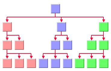
Step 1: Calculating the spanning tree
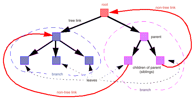
If the graph is disconnected, the layout algorithm chooses a root node for each connected component. Starting from the root node, it traverses the graph to choose the links of the spanning tree. If the graph is a pure tree, all links are chosen. If the graph has cycles, some links are not included as part of the spanning tree. These links are called nontree links, while the links of the spanning tree are called tree links. The nontree links are ignored in step 2 of the algorithm.
In figures
Tree layout in free layout mode with center alignment and flow direction to the right,
Tree layout with flow direction to the bottom, orthogonal link style, and tip-over alignment at some leaf nodes, and
Tree layout in radial layout mode with aspect ratio 1.5, the
root is the node that has no parent node. In the spanning tree, each node except the root has a parent node. All nodes that have the same parent are called
child nodes with respect to the parent and
siblings with respect to one another. Nodes without child nodes are called
leaves. Each child node at a node starts a
subtree (also called a branch of the tree).
A spanning tree shows an example of a spanning tree.
A spanning tree
Step 2: Calculating node positions and link shapes
The layout algorithm arranges the nodes according to the layout mode and the offset and alignment options. In free mode and level mode, the nodes are arranged horizontally or vertically so that all tree links flow roughly in the same direction. In radial layout modes, the nodes are arranged in circles or ellipses around the root so that all tree links flow radially away from the root. Finally, the link shapes are calculated according to the link style and alignment options.
Example of TL
In CSS
The following example is a specification in CSS using the Tree Layout algorithm. Since the Tree Layout places nodes and links, it is usually not necessary to specify an additional link layout in CSS. The specification in CSS can be loaded as a style file into an application that uses the
IlvDiagrammer class.
SDM {
GraphLayout : "true";
LinkLayout : "false";
}
GraphLayout {
graphLayout : "Tree";
layoutMode : "FREE";
flowDirection : "Bottom";
globalLinkStyle : "ORTHOGONAL_STYLE";
globalAlignment : "CENTER";
connectorStyle : "EVENLY_SPACED_PINS";
siblingOffset : "15";
branchOffset : "30";
parentChildOffset : "20";
position : "200,20";
}
However, it is possible to enable the link layout additionally and in this case, the link layout determines the shapes of the links.
In Java
The following code sample uses the
IlvTreeLayout class in Java. This code sample shows how to perform a Tree Layout on a grapher directly without using a diagram component or any style sheet:
...
import ilog.views.*;
import ilog.views.graphlayout.*;
import ilog.views.graphlayout.tree.*;
...
IlvGrapher grapher = new IlvGrapher();
IlvManagerView view = new IlvManagerView(grapher);
... /* Fill in the grapher with nodes and links here */
... /* Suppose we have added rootNode as a node in the grapher */
IlvTreeLayout layout = new IlvTreeLayout();
layout.attach(grapher);
/* Specify the root node, orientation and alignment */
layout.setRoot(rootNode);
layout.setFlowDirection(IlvDirection.Right);
layout.setGlobalAlignment(IlvTreeLayout.CENTER);
try {
IlvGraphLayoutReport layoutReport = layout.performLayout();
int code = layoutReport.getCode();
System.out.println("Layout completed (" +
layoutReport.codeToString(code) + ")");
}
catch (IlvGraphLayoutException e) {
System.err.println(e.getMessage());
}
Important All explanations in the subsequent sections regarding the shape of the links in Tree Layout are valid only if the link layout is disabled.
Generic features and parameters of the TL algorithm
Overview (TL)
The
IlvTreeLayout class supports the following generic features defined in the
IlvGraphLayout class. (See also
Base class parameters and features.)
The following subsections describe the particular way in which these features are used by the Tree Layout subclass.
Allowed time (TL)
The layout algorithm stops if the allowed time setting has elapsed. If the layout stops early because the allowed time has elapsed, the nodes and links are not moved from their positions before the layout call.
The result code in the layout report is IlvGraphLayoutReport.STOPPED_AND_INVALID.
For a description of this layout parameter in the
IlvGraphLayout class, see
Allowed time.
Layout of connected components (TL)
The layout algorithm can use the generic mechanism to lay out connected components. (For more information about this mechanism, see
Layout of connected components). It has, however, a specialized internal mechanism to lay out connected components and, therefore, the generic mechanism is disabled by default.
The generic connected component layout mechanism has the disadvantage that it moves connected components completely. Fixed nodes within a component do not preserve their old position, and the resulting layout can be unstable on incremental changes, depending on which layout instance is used for the component layout.
If the generic connected component layout mechanism is disabled, the algorithm uses its own specialized internal mechanism instead of the generic mechanism to lay out each component as a separate tree. It is faster and more stable on incremental changes than the generic mechanism. Furthermore, it enables the user to set the position of the layout.
Link clipping (TL)
The layout algorithm can use a link clip interface to clip the end points of a link. (See
Link clipping.)
This is useful if the nodes have a nonrectangular shape such as a triangle, rhombus, or circle. If no link clip interface is used, the links are normally connected to the bounding boxes of the nodes, not to the border of the node shapes. See
Using a link clipping interface (TL) for details of the link clipping mechanism.
Link connection box (TL)
The layout algorithm can use a link connection box interface (see
Link connection box) in combination with the link clip interface. If no link clip interface is used, the link connection box interface has no effect. For details, see
Using a link connection box interface (TL).
Spline routing (TL)
The layout algorithm supports the generic spline routing mechanism (see
Spline routing). If the style of a link is orthogonal and the link is a spline, it is routed by the generic spline routing mechanism when it is enabled.
Percentage of completion calculation (TL)
The layout algorithm calculates the estimated percentage of completion. This value can be obtained from the layout report during the run of layout. (For a detailed description of this feature, see
Percentage of completion calculation and
Graph layout event listeners.)
Preserve fixed links (TL)
The layout algorithm does not reshape the links that are specified as fixed.
For more information about link parameters in the
IlvGraphLayout class, see
Preserve fixed links and
Link style (TML).
Preserve fixed nodes (TL)
The layout algorithm does not move the nodes that are specified as fixed.
For more information about node parameters in the
IlvGraphLayout class, see
Preserve fixed nodes.
The layout algorithm ignores fixed nodes completely and also does not route the links that are incident to the fixed nodes. It can result in unwanted overlapping nodes and link crossings. However, this feature is useful for individual, disconnected components that can be laid out independently.
Save parameters to named properties (TL)
The layout algorithm can save its layout parameters into named properties. This can be used to save layout parameters to
.ivl files. (For a detailed description of this feature, see
Save parameters to named properties and
Saving layout parameters and preferred layouts.)
Stop immediately (TL)
The layout algorithm stops after cleanup if the method
stopImmediately is called. (For a description of this method in the
IlvGraphLayout class, see
Stop immediately.) If the layout stops early because the allowed time has elapsed, the nodes and links are not moved from their positions before the layout call, and the result code in the layout report is
IlvGraphLayoutReport.STOPPED_AND_INVALID.
Specific parameters (for all tree layout modes)
The following parameters are specific to the
IlvTreeLayout class. They apply to all layout modes.
Root node (TL)
The final layout is influenced mainly by the choice of the root node.
The root node is placed in a prominent position. For example, in a top-down drawing with free layout mode, it is placed at the top of the tree. With a radial layout mode, it is placed at the center of the tree.
The spanning tree is calculated starting from the root node. If the graph is disconnected, the layout algorithm needs one root node for each connected component.
The layout algorithm automatically selects a root node when needed. It uses a heuristic that calculates preferences for all nodes to become a root. It chooses the node with the highest preference. The heuristic gives nodes without incoming links the highest preference and leaf nodes without outgoing links the lowest preference. Hence, in a directed tree, the canonical root is always chosen automatically.
It is possible to influence the choice of the root node.
To set a node explicitly as the root:
In CSS
Specify a rule that selects the node, for instance:
#node1 {
Root: "true";
}
In Java
Use the method:
void setRoot(Object node);
In this case, the node argument must be a graphic node (subclass of IlvGraphic).
It gives the node the maximum preference to become the root during layout. If only one node is specified in this way, the algorithm selects this node. If several nodes of the same connected component are specified in this way, the layout algorithm chooses one of them as the root.
For experts: additional options for root nodes (TL)
The layout algorithm manages a list of the root nodes that have been specified by the setRoot method.
In Java
To obtain the nodes in this list, use the method:
Enumeration getSpecRoots();
After layout, you can also retrieve the list of root nodes that were used by the algorithm. This list is not necessarily the same as the list of specified roots. For instance, it contains the chosen root nodes if none were specified or if too many were specified.
In Java
To obtain the root nodes that were used by the algorithm, use the method:
Enumeration getCalcRoots();
This example shows how to iterate over the calculated root nodes and print the root node preferences:
In Java
Enumeration e = layout.getCalcRoots();
while (e.hasMoreElements()) {
node = e.nextElement();
System.out.println("Preference:" + layout.getRootPreference(node));
}
To directly manipulate the root node preference value of an individual node:
In CSS
Write a rule to select the node:
#node1 {
RootPreference: "1000";
}
In Java
Use the method:
setRootPreference(Object node, int preference);
In this case, the layout uses the specified value instead of the heuristically calculated preference for the node. The normal preference value must be 0 - 10000. Specifying a root node explicitly corresponds to setting the preference value to 10000. If you want to prohibit a node from becoming the root, specify a preference value of zero ( 0 ).
A negative preference value indicates that the layout algorithm must recalculate the root node preference using the heuristic. If a root was specified by the setRoot method but this node must no longer be the root in subsequent layouts, use the following call to clear the root node setting:
layout.setRootPreference(node, -1);
This call also removes the node from the list of specified roots.
Position parameters (TL)
To set the position of the upper left corner of the layout to (10, 10):
In CSS
Specify:
GraphLayout {
position : "10,10";
rootPosition : "false";
}
In Java
In Java, use the method:
layout.setPosition(new IlvPoint(10, 10), false);
If the graph consists of only a single tree, it is often more convenient to set the position of the root node instead. To do so:
In CSS
Specify in the GraphLayout section:
GraphLayout {
position : "10,10";
rootPosition : "true";
}
In Java
Use the same method and pass true instead of false:
layout.setPosition(point, true);
If no position is specified, the layout keeps the root node at its previous position.
Using compass directions for positional layout parameters (TL)
The compass directions north, south, east, and west are used to simplify the explanations of the layout parameters. The center of the root node of a tree is considered the north pole.
In nonradial layout modes, the link flow direction always corresponds to south. If the root node is placed at the top of the drawing, north is at the top, south at the bottom, east to the right, and west to the left. If the root node is placed at the left border of the drawing, north is to the left, south to the right, east at the top, and west at the bottom.
In radial layout modes, the root node is placed in the center of the drawing. The meaning of north and south depends on the position relative to the root: the north side of the node is the side closer to the root and the south side is the side further away from the root. The east direction is counterclockwise around the root and the west direction is clockwise around the root. It is similar to a cartographic map of a real globe that shows the area of the north pole as if you were looking down at the top of the globe.
Compass directions are used to provide uniform naming conventions for certain layout options. They occur in the alignment options, the level alignment option, and the east-west neighboring feature, which are explained later. In
Flow directions and
Radial layout mode, the compass icons show the compass directions in these drawings.
Layout modes (TL)
The tree layout algorithm has several layout modes. The following example shows how to specify the layout mode.
In CSS
Add to the GraphLayout section:
layoutMode: "FREE";
In Java
Use the method:
void setLayoutMode(int mode);
The available layout modes are:
IlvTreeLayout.FREE (the default)
IlvTreeLayout.LEVEL IlvTreeLayout.RADIAL IlvTreeLayout.ALTERNATING_RADIAL IlvTreeLayout.BALLOON IlvTreeLayout.TIP_OVER IlvTreeLayout.TIP_ROOTS_OVER IlvTreeLayout.TIP_LEAVES_OVER IlvTreeLayout.TIP_ROOTS_AND_LEAVES_OVER In CSS, you omit the prefix IlvTreeLayout when specifying the value of the layout mode.
Layout modes of the TL algorithm
Describes the characteristics and the layout parameters of each layout mode in the TL algorithm.
Describes how the free layout mode organizes nodes and describes the parameters of this mode.
Describes how the level layout mode organizes nodes and describes the parameters of this mode.
Describes how radial layout modes organize nodes and describes the parameters of these modes.
Describes how balloon layout mode organizes nodes and describes the parameters of this mode.
Describes the need for tip-over layout modes and how they operate.
Describes how the recursive mode organizes nodes and describes the parameters of this mode.
Free layout mode
Describes how the free layout mode organizes nodes and describes the parameters of this mode.
Describes how the free layout mode organizes nodes.
Describes the flow direction parameter of the free layout mode.
Describes the alignment parameter of the free layout mode.
Describes the link style parameter of the free layout mode.
Describes the connector style parameter of the free layout mode and how to use it with two interfaces.
Describes how to use the link connection box interface in the free layout mode.
Describes how to use the link clipping interface in the free layout mode.
Describes how to use the spacing parameter of the free layout mode.
Overview
The free layout mode arranges the child nodes of each node starting recursively from the root so that the links flow roughly in the same direction. For instance, if the link flow direction is top-down, the root node is placed at the top of the drawing. Siblings (nodes that have the same parent) are justified at their top borders, but nodes of different tree branches (nodes with different parents) are not justified.
To set the free layout mode:
In CSS
Add to the GraphLayout section:
layoutMode: "FREE";
In Java
Call:
layout.setLayoutMode(IlvTreeLayout.FREE);
Flow direction
The flow direction parameter specifies the direction of the tree links. The compass icons show the compass directions in these layouts.
Flow directions
If the flow direction is to the bottom, the root node is placed at the top. Each parent node is placed above its child nodes, which are normally arranged horizontally. This tip-over alignment is an exception.
If the flow direction is to the right, the root node is placed at the left. Each parent node is placed to the left of its child nodes, which are normally arranged vertically.
To specify the flow direction:
In CSS
Add to the GraphLayout section, for instance
flowDirection: "Left";
In Java
Use the method:
void setFlowDirection(int direction);
The valid values for the flow direction are:
IlvDirection.Right (the default)
IlvDirection.Left IlvDirection.Bottom IlvDirection.Top In CSS, you omit the prefix IlvDirection when specifying the value of the flow direction.
Alignment parameter
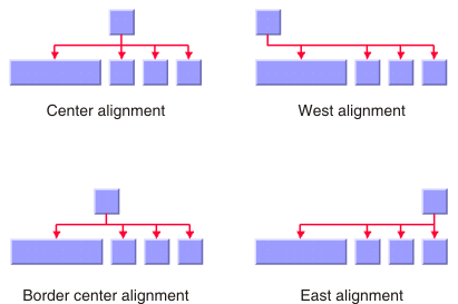
The alignment option controls how a parent is placed relative to its child nodes. The alignment can be set globally, in which case all nodes are aligned in the same way, or locally on each node, with the result that different alignments occur in the same drawing.
Alignment options
Global alignment
To set the global alignment:
In CSS
For example, add to the GraphLayout section:
globalAlignment: "CENTER";
In Java
Use the method:
void setGlobalAlignment(int alignment);
The valid values for the global alignment are:
IlvTreeLayout.CENTER (the default)
The parent is centered over its child nodes, taking the center of the child nodes into account.
IlvTreeLayout.BORDER_CENTER The parent is centered over its child nodes, taking the border of the child nodes into account. If the size of the first and the last child varies, the border center alignment places the parent closer to the larger child than to the default center alignment.
IlvTreeLayout.EAST IlvTreeLayout.WEST IlvTreeLayout.TIP_OVER_EAST The child nodes are arranged sequentially instead of in parallel and the parent node is placed with an offset to the child nodes. The child nodes are to the east of the parent node. For details, see
Tip-over alignment.
IlvTreeLayout.TIP_OVER_WEST The child nodes are arranged sequentially instead of in parallel and the parent node is placed with an offset to the child nodes. The child nodes are to the west of the parent node. For details, see
Tip-over alignment.
IlvTreeLayout.TIP_OVER_EAST_WEST The child nodes are arranged sequentially instead of in parallel and the parent node is placed with an offset to the child nodes. The child nodes are arranged on both sides of the parent node. The first child node is placed to the east. Subsequent child nodes are placed to the east or the west, such that the space used on both sides is roughly the same; that is, the sum of the heights of the subtrees to the east is approximately the same as that of the subtrees to the west. For details, see
Tip-over alignment.
IlvTreeLayout.TIP_OVER_BOTH_SIDES The child nodes are arranged sequentially instead of in parallel. Whereas the alignment
TIP_OVER_EAST or
TIP_OVER_WEST arranges all child nodes on the same side of the parent, this alignment arranges the child nodes on both sides of the parent. Unlike TIP_OVER_EAST_WEST alignment, this style does not try to optimize the space used on both sides, but always places the odd-numbered child nodes on the west and the even-numbered on the east. Each pair of child nodes, one on the west and one on the east, has its odd and even nodes aligned with each other. For details, see
Tip-over alignment.
IlvTreeLayout.MIXED Each parent node can have a different alignment. The alignment of each individual node can be set with the result that different alignments can occur in the same graph.
In CSS, you omit the prefix IlvTreeLayout when specifying the value of the alignment.
Alignment of individual nodes
All nodes have the same alignment unless the global alignment is set to MIXED. Only when the global alignment is set to MIXED can each node have an individual alignment style.
Different alignments mixed in the same drawing
To specify the alignment of an individual node:
In CSS
First set the global alignment to MIXED, then specify a rule that selects the node; for example:
GraphLayout {
globalAlignment: "MIXED";
}
#node1 {
Alignment: "EAST";
}
In Java
Use the methods:
void setAlignment(Object node, int alignment);
int getAlignment(Object node);
The valid values for alignment are:
IlvTreeLayout.CENTER (the default value)
IlvTreeLayout.BORDER_CENTER IlvTreeLayout.EAST IlvTreeLayout.WEST IlvTreeLayout.TIP_OVER_EAST IlvTreeLayout.TIP_OVER_WEST IlvTreeLayout.TIP_OVER_EAST_WEST IlvTreeLayout.TIP_OVER_BOTH_SIDES Tip-over alignment
Normally, the child nodes of a node are placed in a parallel arrangement with siblings as direct neighbors of each other. Tip-over alignments mean a sequential arrangement of the child nodes instead.
Normal alignment and a tip-over alignment
Tip-over alignment is useful when the tree has many leaves. With normal alignment, a tree with many leaves would result in the layout being wide. If the global alignment style is set to tip-over, the drawing is tall rather than wide. To balance the width and height of the drawing, you can set the global alignment to mixed.
In Java
For example:
layout.setGlobalAlignment(IlvTreeLayout.MIXED);
Also, you can set the individual alignment to tip-over for some parents with a high number of child nodes as follows:
layout.setAlignment(parent, IlvTreeLayout.TIP_OVER_EAST);
Tip-over alignments can be specified explicitly for some or all of the nodes. Tree Layout offers layout modes that automatically determine when to tip over, giving a drawing that fits into a specified aspect ratio. These layout modes are described in
Tip-over layout modes.
Tip-over-east alignment arranges the nodes on the east side of the center line that starts at the parent node. The tip-over-west alignment arranges the nodes on the west side of that line. There are also two variants that distribute the subtrees on both sides of that line. You can specify these variants at a parent node with a high number of child nodes by the following code:
layout.setAlignment(parent, IlvTreeLayout.TIP_OVER_EAST_WEST);
or:
layout.setAlignment(parent, IlvTreeLayout.TIP_OVER_BOTH_SIDES);
The following figures show the difference between Tip-over-east-west and tip-over-both-sides alignments.
| |
Tip-over-east-west alignment | Tip-over-both-sides alignment |
Tip-over alignment works well with the orthogonal link style; see
Link style (TL). The following figure shows the difference between tip over on one side and tip over on two sides. Tip-over alignments are specified for the red nodes; the blue nodes have center alignment.
Tip-over alignments
Child alignments
Global alignment is valid for all nodes. The alignment specified at a node is valid for all child nodes of that node. Additionally, you can specify exceptions for certain nodes that are aligned differently than all other child nodes. This is useful for organization chart displays. In an organization chart that shows a management hierarchy, some of the people shown do not belong to the hierarchy. Instead, they are associated with a particular member of the hierarchy. An example could be a secretary associated with a manager of a company. In an organization chart tree, the node representing the secretary is normally displayed close to the node of the manager, but is not mixed with the child nodes that represent the normal workers who report to that manager.
To set the child alignment of a specific node:
In CSS
#node1 {
ChildAlignment: "EAST_NEIGHBOR";
}
In Java
Use the methods:
void setChildAlignment(Object node, int alignment);
int getChildAlignment(Object node);
The following values are valid for child alignment:
IlvTreeLayout.UNSPECIFIED (the default value).
No exceptional alignment is specified for the child node. It is aligned like normal child nodes.
IlvTreeLayout.EAST_NEIGHBOR The child node is made a neighbor on the east of its parent.
IlvTreeLayout.WEST_NEIGHBOR The child node is made a neighbor on the west of its parent.
IlvTreeLayout.TIP_OVER_ASSOCIATE_EAST The child node layout is like tip-over-east alignment, but the node appears above all normal child nodes. The normal child nodes can have any alignment. If they also have tip-over-east alignment, you can distinguish the associate node by using a different spacing. See
Spacing parameters.
IlvTreeLayout.TIP_OVER_ASSOCIATE_WEST The child node layout is like tip-over-west alignment, but the node appears above all normal child nodes. The normal child nodes can have any alignment. If they also have tip-over-west alignment, you can distinguish the associate node by using a different spacing. See
Spacing parameters.
IlvTreeLayout.TIP_OVER_ASSOCIATE_BOTH_SIDES The child node layout is like tip-over-both-sides alignment, that is, alternating on the east and the west, but the node appears above all normal child nodes. The normal child nodes can have any alignment. If they also have tip-over-both-sides alignment, you can distinguish the associate node by using a different spacing. See
Spacing parameters.
In CSS, omit the prefix IlvTreeLayout when you specify the value of the alignment.
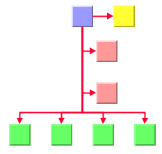
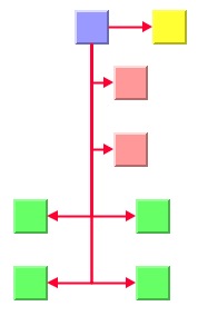
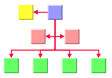
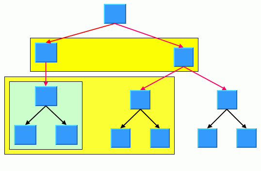
In the following figures, the yellow nodes have child alignments EAST_NEIGHBOR or WEST_NEIGHBOR, and the red nodes have child alignments TIP_OVER_ASSOCIATE_EAST or TIP_OVER_ASSOCIATE_BOTH_SIDES. The green nodes have unspecified child alignments, that is, they are aligned with the global alignment style.
| |
Alignments shown are for yellow node: east neighbor, for red nodes: tip over associate east, and for green nodes: center | Alignments shown are for yellow node: east neighbor, for red nodes: tip over associate east, and for green nodes: tip over both sides |
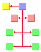
| |
Alignments shown are for yellow node: west neighbor, for red nodes: tip over associate both sides, and for green nodes: center | Alignments shown are for yellow node: west neighbor, for red nodes: tip over associate both sides, and for green nodes: tip over both sides |
Link style (TL)
When using the Tree layout, it is preferable to use link connectors of type
IlvFreeLinkConnector and links of type
IlvPolylineLinkImage or
IlvSplineLinkImage. The links can be straight or have a specific shape with intermediate points. You can specify that the links be reshaped into an “orthogonal” form. You can set the link style globally, in which case all links have the same shape, or locally on each link, in which case different link shapes occur in the same drawing.
Link style and link shapes
Link styles work only when you use links that can be reshaped. Subclasses of
IlvPolylineLinkImage or of
IlvSplineLinkImage, (such as
IlvGeneralLink ) can be reshaped. Furthermore, link styles work only if free link connectors are installed. Free link connectors are subclasses of
IlvFreeLinkConnector. If you use a diagram component, the free link connectors are automatically installed when necessary unless specified differently. If you call layout in Java™ on an
IlvGrapher instance directly, the layout algorithm may raise an
IlvInappropriateLinkException if links are neither a subclass of
IlvPolylineLinkImage nor of
IlvSplineLinkImage, or if connectors are not a subclass of
IlvFreeLinkConnector. In this case, you can use the methods
EnsureAppropriateLinkTypes,
EnsureAppropriateLinkConnectors, or
EnsureAppropriateLinks defined in
IlvGraphLayoutUtil to replace inappropriate links or link connectors automatically, either before layout or when the
IlvInappropriateLinkException is caught. For details on these methods, see the
Java API Reference Manual. For details on the graph model, see
Using the graph model.
Global link style
To specify the global link style:
In CSS
Add this statement to the GraphLayout section:
globalLinkStyle: "STRAIGHT_LINE_STYLE";
In Java
Use the method:
void setGlobalLinkStyle(int style);
The valid values for style are:
IlvTreeLayout.NO_RESHAPE_STYLE None of the links is reshaped in any manner.
IlvTreeLayout.STRAIGHT_LINE_STYLE IlvTreeLayout.ORTHOGONAL_STYLE IlvTreeLayout.MIXED_STYLE Each link can have a different link style. The style of each individual link can be set to have different link shapes occurring on the same graph.
In CSS, you omit the prefix IlvTreeLayout when specifying the value of the link style.
Individual link style
All links have the same style of shape unless the global link style is MIXED_STYLE. Only when the global link style is set to MIXED_STYLE can each link have an individual link style.
Different link styles mixed in the same drawing
To specify the style of an individual link:
In CSS
First set the global link style to MIXED_STYLE, then specify a rule that selects the link, for instance:
GraphLayout {
globalLinkStyle: "MIXED_STYLE";
}
#link1{
LinkStyle: "ORTHOGONAL_STYLE";
}
In Java
Use the methods:
The valid values for style are:
IlvTreeLayout.STRAIGHT_LINE_STYLE (the default)
IlvTreeLayout.NO_RESHAPE_STYLE IlvTreeLayout.ORTHOGONAL_STYLE Connector style (TL)
The layout algorithm automatically positions the end points of links (the connector pins) at the nodes. The connector style parameter specifies how these end points are calculated for the outgoing links at the parent node.
By default, the connector style determines how the connection points of the links are distributed on the border of the bounding box of the nodes, symmetrically with respect to the middle of each side.
Connector styles
To specify the connector style:
In CSS
Add to the GraphLayout section:
connectorStyle: "CLIPPED_PINS";
In Java
Use the method:
void setConnectorStyle(int style);
The valid values for style are:
IlvTreeLayout.CENTERED_PINS The end points of the links are placed in the center of the border where the links are attached.
IlvTreeLayout.CLIPPED_PINS Each link pointing to the center of the node is clipped at the node border. The connector pins are placed at the points on the border where the links are clipped. This style affects straight links. It behaves like centered connector pins for orthogonal links.
IlvTreeLayout.EVENLY_SPACED_PINS The connector pins are evenly distributed along the node border. This style works for straight and orthogonal links.
IlvTreeLayout.AUTOMATIC_PINS The connector style is selected automatically depending on the link style and the layout mode. In nonradial modes, the algorithm always chooses centered pins. In radial layout modes, it chooses clipped pins.
In CSS, you omit the prefix IlvTreeLayout when specifying the value of the connector style.
NOTE The connector style parameter requires link connectors at the nodes of an
IlvGrapher that allow connector pins to be placed freely at the node border. It is recommended that you use
IlvFreeLinkConnector for link connectors to be used in combination with
IlvGrapher objects. If you use a diagram component, the free link connectors are automatically installed when needed, unless specified differently.
The connector style, the link connection box interface, and the link clip interface work together in the following way: by applying the connector style, the proposed connection points are calculated on the rectangle obtained from the link connection box interface (or on the bounding box of the node, if no link connection box interface was specified). Then, the proposed connection point is passed to the link clip interface and the returned connection points are used to connect the link to the node.
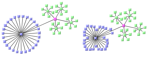
The following figure shows an example of the combined effect.
If the links are clipped at the pink node in the figure (left), they appear unsymmetrical with respect to the node shape, because the relevant part of the node (here: the upper rhombus) is not in the center of the bounding box of the node, but the proposed connection points are calculated with respect to the bounding box.
Combined effect of clipping and link connection box
It can be corrected by using a link connection box interface to explicitly specify a smaller connection box for the relevant part of the node (previous figure, right) such that the proposed connection points are placed symmetrically at the upper rhombus of the node.
Using a link connection box interface (TL)
Sometimes it is necessary to place the connection points on a rectangle smaller or larger than the bounding box, possibly in a nonsymmetric way. For instance, it can happen when labels are displayed below or above nodes.
You can modify the position of the connection points of the links by providing a class that implements the
IlvLinkConnectionBoxInterface. An example for the implementation of a link connection box interface is in
Link connection box. To set a link connection box interface in Java™, call:
void setLinkConnectionBoxInterface(IlvLinkConnectionBoxInterface interface)
The link connection box interface provides each node with a link connection box and a tangential shift offset that defines how much the connection points are “shifted” tangentially depending on which side the links connect.
The following figure illustrates the effects of customizing the connection box when the connector style is evenly spaced.
Effect of connection box interface
On the left is the result without any connection box interface. The middle picture shows the effect if the connection box interface returns the dashed rectangle for the blue node but the tangential offset at all sides of the node is 0. Notice that the outgoing links are spaced according to the dashed rectangle, which appears too wide for the blue node in this situation. The picture on the right shows the effect of the connection box interface if, in addition, a positive tangential offset was specified for the bottom side and a negative offset was specified for the left side of the blue node.
Using a link clipping interface (TL)
By default, the Tree Layout places the connection points of links at the border of the bounding box of the nodes.
If the node has a nonrectangular shape such as a triangle, rhombus, or circle, you may want the connection points to be placed exactly on the border of the shape. This can be achieved by specifying a link clip interface. The link clip interface allows you to correct the calculated connection point so that it lies on the border of the shape. The following figure shows an example.
Effect of link clipping interface
You can modify the position of the connection points of the links by providing a class that implements the
IlvLinkClipInterface. An example for the implementation of a link clip interface is in
Link clipping. To set a link clip interface in Java™, call:
void setLinkClipInterface(IlvLinkClipInterface interface)
NOTE In addition to the link clip interface, you can use the
IlvClippingLinkConnector. This special link connector updates the clipped connection points automatically during interactive node movements.
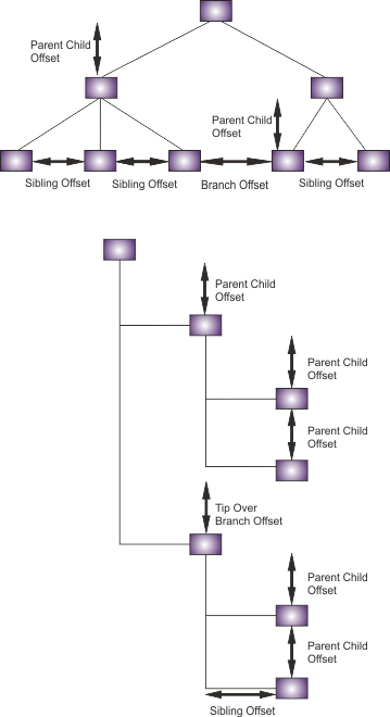
Spacing parameters
The spacing of the layout is controlled mainly by three spacing parameters: the distance between a parent and its child nodes, the minimum distance between siblings, and the minimum distance between nodes of different branches. For example, if the flow direction is to the top or bottom, the offset between parent and child nodes is vertical; the sibling offset and the branch offset are horizontal.
For tip-over alignment, an additional spacing parameter is provided: the minimum distance between branches starting at a node with tip-over alignment. This offset is always orthogonal to the normal branch offset. If the flow direction is to the top or bottom, the tip-over branch offset is vertical.
Spacing parameters
To specify the spacing parameters:
In CSS
Specify in the GraphLayout section:
parentChildOffset: "30.0";
siblingOffset: "15.0";
branchOffset: "20.0";
tipOverBranchOffset: "30.0";
In Java
In Java™, use the methods:
void setParentChildOffset(float offset);
void setSiblingOffset(float offset);
void setBranchOffset(float offset);
void setTipOverBranchOffset(float offset);
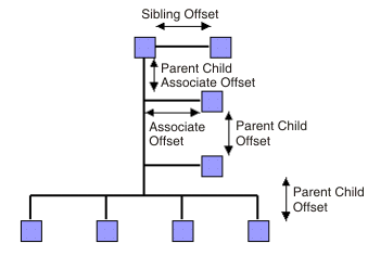
Associate nodes that have a tip-over-associate child alignment use special spacing parameters: the associate offset is the distance between the associate node and the center line that starts at the parent node. The parent child offset is the distance between the parent node and the first associate node.
Spacing of child alignments
To specify the associate spacing parameters:
In CSS
Specify in the GraphLayout section:
parentChildAssociateOffset: "20.0";
associateOffset: "25.0";
In Java
Use the methods:
void setParentChildAssociateOffset(float offset);
void setAssociateOffset(float offset);
For experts: additional spacing parameters
The spacing parameters normally specify the minimum offsets between the node borders. Hence, the layout algorithm places the nodes such that they do not overlap. You can also specify that the layout must ignore the node sizes.
In CSS
Add to the GraphLayout section:
respectNodeSizes: "false";
In Java
In Java, call:
layout.setRespectNodeSizes (false);
In this case, the spacing parameters are interpreted as the minimum distances between the node centers, and the node sides are not taken into account during the layout. However, if the specified offset parameters are now smaller than the node size, the nodes and links overlap. It often happens with orthogonal links in particular. It makes sense to use this option only if all nodes have approximately the same size, all links are straight, and the spacing parameters are larger than the largest node.
If the link style is orthogonal, the shape of the links from the parent to its child nodes looks like a fork (see
Different alignments mixed in the same drawing). The position of the bend points in this shape can be influenced by the
orthogonal fork percentage, a value
0 -
100. It is a percentage of the parent-child offset. If the orthogonal fork percentage is
0, the link shape forks directly at the parent node. If the percentage is
100, the link shape forks at the child node. A good choice is
25 -
75. This percentage can be set.
In CSS
Add a statement such as:
orthForkPercentage: "66.6";
In Java
Use the method:
void setOrthForkPercentage(float percentage);
If the link style is not orthogonal, links can overlap neighboring nodes. It happens only in a few cases, for example, when a link starts at a small node that is neighboring a large node. This deficiency can be fixed by increasing the branch offset. However, it influences the layout globally, affecting nodes without that deficiency. To avoid a global change, you can change the overlap percentage instead, which is a value 0 - 100. This value is used by an internal heuristic of the layout algorithm that considers a node to be smaller by this percentage. The default percentage is 30. It results usually in better usage of the space. For small nodes neighboring large nodes, you are recommended to decrease the overlap percentage or to set it to 0. By taking this action, you disable this heuristic and avoid links overlapping nodes.
To set the overlap percentage:
In CSS
Add a statement such as:
overlapPercentage: "33.3";
In Java
Use the method:
void setOverlapPercentage(float percentage);
NOTE Always set the orthogonal fork percentage to a value larger than the value of the overlap percentage.
Effect of using the overlap percentage
Level layout mode
Describes how the level layout mode organizes nodes and describes the parameters of this mode.
Describes how the level layout mode organizes nodes.
Describes the layout parameters of the level layout mode.
Describes the level alignment parameters of the level layout mode.
Overview
The level layout mode partitions the node into levels and arranges the levels horizontally or vertically. The root is placed at level 0, its child nodes at level 1, the child nodes of those child nodes at level 2, and so on. In contrast to the free layout mode, in level layout mode the nodes of the same level are justified with each other even if they are not siblings (that is, they do not have the same parent).
To set the level layout mode:
In CSS
Add to the GraphLayout section:
layoutMode: "LEVEL";
In Java
Call the method:
layout.setLayoutMode(IlvTreeLayout.LEVEL);
The following figure shows the same graph in free layout mode and in level layout mode.
Free layout mode and level layout mode
General parameters
Most layout parameters that work for the free layout mode work as well for the level layout mode. You can set the flow direction, the spacing offsets, the global or individual link style, and the global or individual alignment. See
Free layout mode for details.
The differences from the free layout mode are:
Tip-over alignment does not work in level layout mode.
The parent-child offset parameter controls the spacing between the levels. In level layout mode, it is the
minimum distance between parent and its child nodes, while in free layout mode, it is the
exact distance between parent and its child nodes.
The overlap percentage has no effect in level layout mode.
Level alignment
In level layout mode with flow direction to the top or bottom, the nodes are organized in horizontal levels such that the nodes of the same level are placed approximately at the same y-coordinate. The nodes can be justified, depending on whether the top border, the bottom border, or the center of all nodes of the same level must have the same y-coordinate.
In flow direction to the left or right, the nodes are organized in vertical levels approximately at the same x-coordinate. The nodes of the same level can be justified at the left border, at the right border, or at the center.
To distinguish the level alignment independently from the flow direction, the directions north and south are used (see
Using compass directions for positional layout parameters (TL)). The north border of a node is the border that is closer to the level where its parent is placed, and the south border of a node is the border that is closer to the level where its child nodes are placed. If the flow direction is to the bottom, the level alignment north means that the nodes are justified at the top border, and south means that the nodes are justified at the bottom border. If the flow direction is to the top, north and south are inverted: north means the bottom border and south means the top border. If the flow direction is to the right, then north means the left border and south means the right border.
Level alignment
To specify the level alignment:
In CSS
Add to the GraphLayout section:
levelAlignment: "NORTH";
In Java
In Java™, use the method:
void setLevelAlignment(int alignment);
The valid values for alignment are:
IlvTreeLayout.CENTER (the default)
IlvTreeLayout.NORTH IlvTreeLayout.SOUTH In CSS, you omit the prefix IlvTreeLayout when specifying the value of the level alignment.
Radial layout modes
Describes how radial layout modes organize nodes and describes the parameters of these modes.
Describes how radial layout mode organizes nodes.
Describes how alternating radial mode organizes nodes.
Describes the layout parameters of radial layout modes.
Describes the aspect ratio parameter of alternating radial mode.
Describes the spacing parameters of radial modes.
Describes some tips and tricks for expert users.
Radial mode
Radial layout mode partitions the node into levels and arranges the levels in circles around the root node. The following figure shows an example of radial layout mode. The compass icons show the compass directions in this drawing.
Radial layout mode
To set radial layout mode:
In CSS
Specify in the GraphLayout section:
layoutMode: "RADIAL";
In Java
Call the method:
layout.setLayoutMode(IlvTreeLayout.RADIAL);
Alternating radial mode
If levels of the graph contain many nodes, it is sometimes necessary to increase the radius of the circular level to provide enough space on the circumference of the circle for all the nodes. It can result in a considerable distance from the previous level. To avoid it, there is an alternating radial mode. Alternating radial mode places the nodes of a level alternating between two circles instead of one circle, resulting in better use of the space of the layout.
Alternating radial mode uses two circles only when necessary. For many small and light trees, there is no difference from normal radial mode. Alternating radial mode affects only large graphs with many child nodes.
To set alternating radial layout mode:
In CSS
Specify in the GraphLayout section:
layoutMode: "ALTERNATING_RADIAL";
In Java
Call the method:
layout.setLayoutMode(IlvTreeLayout.ALTERNATING_RADIAL);
Radial layout mode (right) and alternating radial layout mode (left)
General parameters
Most layout parameters that work for free and level layout mode work as well for radial layout modes. You can set the spacing offsets, the level alignment, the global or individual link style, and the global or individual alignment. See
Free layout mode and
Level layout mode for details.
Radial layout modes differ from other layout modes as follows:
Tip-over alignment does not work in radial layout modes.
The orthogonal link style does not work in radial layout modes.
The clipped connector style is always used.
The parent-child offset parameter controls the minimum distance between the circular levels. However, it is sometimes necessary to increase the offset between circular levels to obtain enough space on the circle to place all nodes of a level.
The level alignment
north indicates alignment at the inner border of the circular level (that is, towards the root), and the level alignment
south indicates alignment at the outer border of the circular level (that is, away from the root).
The level alignments
north and
south sometimes result in overlapping nodes.
The overlap percentage has no effect in radial layout modes.
Aspect ratio
If the drawing area is not a square, arranging the levels as circles is not always the best choice. You can specify the aspect ratio of the drawing area to better fit the layout to the drawing area. In this case, the algorithm uses ellipses instead of circles. See
Tree layout in radial layout mode with aspect ratio 1.5 for an example.
To specify the aspect ratio:
In CSS
Add this, for instance, to the GraphLayout section:
aspectRatio: "0.7";
In Java
In Java™, there are several possibilities.
If the drawing area is a view (a subclass of IlvManagerView ), you can use the method:
void setAspectRatio(IlvManagerView view);
If the drawing area is specified only as a rectangle, use:
void setAspectRatio(IlvRect rect);
If neither a view nor a rectangle is specified, you can calculate the aspect ratio from the width and height of the drawing area as aspectRatio = width/height and use the method:
void setAspectRatio(float aspectRatio);
Spacing parameters
The spacing parameters of radial layout modes are controlled by the same CSS statements and methods as used for free and level layout modes.
void setParentChildOffset(float offset);
void setSiblingOffset(float offset);
void setBranchOffset(float offset);
The sibling and branch offsets are minimum distances tangential to the circles or ellipses, while the parent-child offset is a minimum distance radial to the circles or ellipses.
The following figure shows the spacing parameters in radial layout mode.
Spacing parameters in radial layout mode
Tips and tricks
Adding an invisible root to the layout
If the graph contains several trees that are disconnected from each other, the layout places them individually next to each other. Each connected component has its own radial structure with circular layers. However, sometimes it is appropriate to fit all connected components into a single circular layer structure. Conceptually, it is done by adding an invisible root at the center and connecting all disconnected trees to this root. Figure
Layout of connected components without and with an invisible root shows the effect of using an invisible root. It works only if the generic mechanism to lay out connected components is disabled.
To add an invisible root to the layout:
In CSS
In CSS, specify:
layoutOfConnectedComponentsEnabled: "false";
invisibleRootUsed: "true";
In Java
Call the method:
layout.setLayoutOfConnectedComponentsEnabled(false);
layout.setInvisibleRootUsed(true);
Layout of connected components without and with an invisible root
Even spacing for the first circle
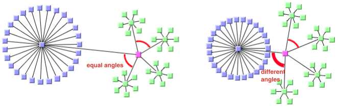
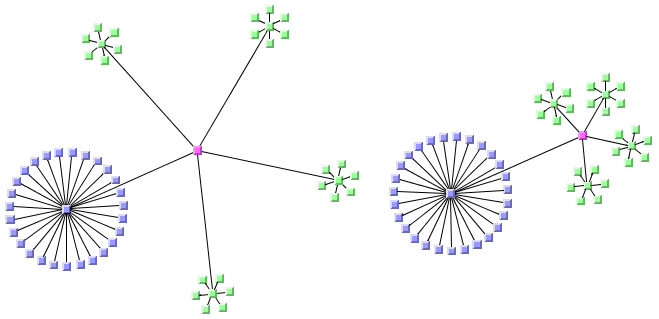
Radial mode is designed to optimize the space such that the circles have a small radius and the overall space for the entire layout is small. To achieve this result, the layout algorithm can create larger gaps on the inner circles for better space usage of the outer circles. It can produce unevenly spaced circles, most notably for the first circle where all nodes have the same parent node.
To avoid this effect, you can force the nodes to be evenly spaced on the entire first circle. Depending on the structure of the graph, it can cause the overall layout to waste more space on the other circles but it can produce a more pleasing graph.
To enable even spacing:
In CSS
Specify:
firstCircleEvenlySpacing: "true";
In Java
Call the method:
layout.setFirstCircleEvenlySpacing (true);
Evenly and unevenly spaced first circle
For experts: forcing all levels to alternating
When the layout mode ALTERNATING_RADIAL is used, the layout checks whether the alternating node arrangement of a level saves space. If it does not save space, the layout uses the normal radial arrangement. Therefore, for many sparse graphs, radial and alternating radial mode yield the same result because the alternating arrangement does not save space for any level. It is possible to disable the space check, that is, to perform an alternating arrangement for all levels even if this results in waste of space.
In CSS
Add to the GraphLayout section:
allLevelsAlternating: "true";
In Java
Call:
layout.setAllLevelsAlternating(true);
For experts: multiple circles per alternating level
When the layout mode ALTERNATING_RADIAL is used, the layout places nodes of the same level alternately into two circles instead of one circle. It is possible to increase the number of circles even more.
In CSS
Add to the GraphLayout section:
numberOfAlternatingCircles: "3"
In Java
Call:
layout.setNumberOfAlternatingCircles(3);
In this case, three circles are used. That means, if the flag allLevelsAlternating is true, the layout places each level of nodes onto three alternating circles. If the allLevelsAlternating flag is false, it checks whether each level requires more space to place the nodes on one circle or on three circles. High values for the number of alternating circles must not be used, because they slow down the algorithm and can produce link crossings.
If you set the number of alternating circles to 0 and the allLevelsAlternating flag is false, then it has a special meaning. In this case, a heuristic tries to calculate the best number of circles per level automatically. As a result, each level might have a different number of circles, depending on the number of nodes and the sibling relationships between the nodes.
For experts: setting a maximum child angle
If a node has many child nodes, they can extend over a major portion of the circle and, therefore, are placed nearly 360 degrees around the node. It can result in links overlapping some nodes. The deficiency can be fixed by increasing the offset between parent and child nodes. However, it affects the layout globally, which means that nodes without the deficiency are also affected. To avoid such a global change, you can limit the maximum angle between the two rays from the parent, if it is not the root, to its two outermost child nodes. This action increases the offset between parent and child nodes only where necessary.
In figure
Maximum child angle, you can see in the layout on the left that many of the links overlap other nodes. In the layout on the right, you can see how this problem was solved by setting a maximum child angle between two rays from a parent to the two outermost child nodes.
Maximum child angle
To set an angle in degrees.
In CSS
Specify:
maxChildrenAngle: "90";
In Java
Use the method:
void setMaxChildrenAngle(int angle);
Recommended values are 30 - 180. Setting the value to 0 means the angle is unrestricted. The calculation of the angle is not precise above 180 degrees or if the aspect ratio is not 1.0.
Balloon layout mode
Describes how balloon layout mode organizes nodes and describes the parameters of this mode.
Describes how balloon layout mode organizes nodes.
Describes the layout parameters of balloon layout mode.
Describes the spacing parameters of balloon layout mode.
Describes some tips and tricks for expert users.
Overview
Balloon layout mode is similar to radial layout mode with the following differences:
Radial layout mode arranges all nodes in circles around the root node; balloon layout mode arranges child nodes in circles around the parent node.
In radial layout mode, there is only one circle center for the entire tree; in balloon layout mode, each subtree has a different circle center.
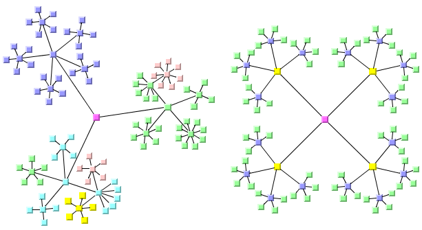
In balloon layout mode, each subtree forms a balloon. The following figure shows examples of balloon layout mode.
Examples of balloon layout mode
To set balloon layout mode:
In CSS
Specify in the GraphLayout section:
layoutMode: "BALLOON";
In Java
In Java™, call:
layout.setLayoutMode(IlvTreeLayout.BALLOON);
General parameters
Many layout parameters such as the root node selection and positioning parameters work as in the other layout modes.
Balloon layout mode differs from the other layout modes as follows:
The flow direction determines the arrangement of disconnected trees, unless the generic mechanism for the layout of connected components is used. The flow direction also determines the angle orientation, which is counterclockwise for flow direction bottom and right, and clockwise for flow direction top and left. The flow direction has no other meaning for the balloon arrangement.
The minimum offset between nodes is determined by the branch offset. The other offset parameters have no effect for the balloon layout mode.
The alignment parameters including level alignment make no sense in balloon layout mode.
The orthogonal link style does not work in balloon layout mode.
The overlap percentage has no effect in balloon layout mode.
Spacing parameters
Branch Offset
Balloon layout mode has minimum spacing only between nodes, and does not distinguish between minimum offsets of siblings, branches, and parent-child relationships. The minimum spacing between nodes is controlled by the branch offset, as in free mode and level mode. The sibling offset and parent-child offset have no effect in balloon layout mode.
To specify the minimum offset between nodes:
In CSS
In CSS, specify in the Graph Layout section:
branchOffset: "20.0";
In Java
In Java™, use the method:
void setBranchOffset(float offset);
Angle Spacing
The angles between sectors of a balloon, and the radius of the balloon have more effect on the spacing of the layout than the minimum offset. A bad choice of sector angles requires larger radii to avoid overlaps, and hence a larger area for the layout. Therefore, the layout offers different angle spacing modes.
In the following figure, the layout on the left uses regular angle spacing and the layout on the right uses proportional angle spacing. On the right, the sector angle of the blue subtree is much larger than the sector angles of each green subtree, since the blue subtree is larger than the green subtrees.
Angle spacing: left: regular, right: proportional (slow)
To specify angle spacing:
In CSS
Add to the Graph Layout section:
balloonAngleSpacing: "REGULAR";
In CSS, there is no IlvTreeLayout prefix when you specify the value of angle spacing.
In Java
In Java™, use the method:
void setBalloonAngleSpacing(int mode);
The valid values for mode are:
IlvTreeLayout.REGULAR
The available angle range at a node is evenly split so that each subtree balloon at the node can occupy the same angle. It looks uniform but tends to waste space if the subtrees are not the same size. See the angle spacing figure, left image.
IlvTreeLayout.FAST_PROPORTIONAL
The available angle range at a node is proportionally split so that larger subtree balloons at the node can occupy larger angles. As a consequence, a larger subtree requires a smaller radius, hence this mode uses less space. The algorithm uses a fast heuristic to calculate the angle ranges. This heuristic is not precise and sometimes produces asymmetric layouts. The quality of the result depends strongly on the choice of start angle. The heuristic runs in linear time.
IlvTreeLayout.PROPORTIONAL
Same as the fast proportional mode: the available angle range at a node is proportionally split so that larger subtree balloons at the node can occupy larger angles. However, the algorithm uses a slow heuristic that is more precise, uses the space even better, and produces symmetric layouts. The quality of the result does not depend on the choice of start angle. The heuristic runs in quadratic time. It is the default mode. See the angle spacing figure, right image.
Radius mode
When the sector angles have been chosen for the subtree balloons, the radius (length of the link from parent to child) must be calculated so that no subtrees overlap. The choice of radius is a trade-off between symmetry and area. Choosing a uniform radius for all child nodes of the same parent often requires much space. See the figure showing examples of uniform and variable radius layouts, upper left image. If the radius is variable, symmetries are lost. As a compromise, you can choose to have a variable radius only for large subtree balloons and keep a uniform radius for all the leaves of a parent. See the figure showing examples of uniform and variable radius layouts, upper right image, where the link towards the blue subtree is longer than the links to the green subtrees. If symmetries are not important, an additional optimization phase can be selected that shifts the balloons closer together. The optimization phase can be applied to subtrees that are not leaves. See the figure showing examples of uniform and variable radius layouts, lower left image. This phase can also be used to shift leaves together. See the figures showing examples of uniform and variable radius layouts, lower right image. In the latter case, the leaves are often rather scattered and no longer on a circle.
Radius mode: left: uniform, right: uniform leaves (larger subtrees have variable radius)
Radius mode: left: optimized uniform leaves, right: optimized variable
To specify the radius mode:
In CSS
In CSS, add to the Graph Layout section:
balloonRadiusMode: "UNIFORM_RADIUS";
In CSS, there is no IlvTreeLayout prefix when you specify the value of the radius mode.
In Java
In Java™, use the method:
void setBalloonRadiusMode(int mode);
The valid values for mode are:
IlvTreeLayout.UNIFORM_RADIUS
The radii of all subtree balloons that are child nodes of the same node are uniform. This mode requires the largest area but also gives the greatest number of symmetries in the layout. However, if the tree is not balanced, it usually wastes much space. See the variable radius figure, upper left image.
IlvTreeLayout.UNIFORM_LEAVES_RADIUS
The radii of all leaves that are child nodes of the same node are uniform, however the radius of a balloon that contains more than one node can vary. This value is better for unbalanced trees since it uses the available space much better. Use this value if symmetries in the layout are important. See the variable radius figure, upper right image.
IlvTreeLayout.VARIABLE_RADIUS
The radius of all different child balloons at the same parent node can vary. It even varies for child nodes of the same node, if these child nodes have different node sizes.
IlvTreeLayout.OPTIMIZED_UNIFORM_LEAVES_RADIUS
The initial placement is done as in uniform leaves radius mode. Additionally, an optimization heuristic shifts subtrees together to reduce the radii. This has the advantage of smaller space requirements but loses symmetries in the diagram. Leaves that have the same parent node still keep the same radius. See the variable radius figure, lower left image.
IlvTreeLayout.OPTIMIZED_VARIABLE_RADIUS
The initial placement is done as in variable radius mode. Additionally, an optimization heuristic shifts subtrees together to reduce the radii. It has the advantage of smaller space requirements but loses symmetries in the diagram. It affects even leaves of the same parent, hence they can end up rather scattered around the parent. See the variable radius figure, lower right image.
Tips and tricks
Start angle
If you want to rotate a balloon layout, you can modify the start angle of the layout. This is the angle where the first child node is placed at the root. All subtrees rotate with this start angle. The angle spacing value FAST_PROPORTIONAL is not stable with respect to the start angle: the layout can change considerably when you change the start angle. The other angle spacing values are stable: they rotate the entire layout. The start angle must be 0° - 360°.
To change the start angle:
In CSS
In CSS, specify:
balloonStartAngle: "90";
In Java
In Java™, call:
layout.setBalloonStartAngle(90);
Angle range
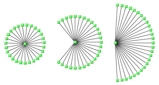
Normally, child nodes are placed all around their parent node; they occupy an angle range of 360° around the parent. It is possible to limit the angle range available for child nodes. In the following figure, the angle range for child nodes is 360° degrees on the left, 270° in the middle and 180° on the right. You can specify a different angle range for the root, for nodes that have only leaves, and for inner nodes of the tree.
The effect of the balloon child angle: left: 360, middle: 270, right: 180
To change the angle ranges:
In CSS
In CSS, specify:
balloonRootChildrenAngle: "270";
balloonInnerChildrenAngle: "270";
balloonLeafChildrenAngle: "270";
In Java
In Java™, call:
layout.setBalloonRootChildrenAngle(270);
layout.setBalloonInnerChildrenAngle(270);
layout.setBalloonLeafChildrenAngle(270);
Disconnected trees
Multiple disconnected trees can be laid out together by the balloon layout mode. By default, they are arranged in a sequence according to the flow direction of the layout. As an alternative, you can choose the generic disconnected graph spacing. For details, see
Layout of connected components (TL). Another alternative, as for radial layout mode, is to introduce an invisible root. In this case, the balloons are arranged around the invisible root.
To add an invisible root to the layout:
In CSS
In CSS, specify:
layoutOfConnectedComponentsEnabled: "false";
invisibleRootUsed: "true";
In Java
Call:
layout.setLayoutOfConnectedComponentsEnabled(false);
layout.setInvisibleRootUsed(true);
Tip-over layout modes
Drawing in radial layout mode and free layout mode can be adjusted according to the aspect ratio of the drawing area. To balance the height and depth of the drawing, free layout mode can also use tip-over alignment.
Tip-over alignment can be specified explicitly for individual nodes. The Tree Layout algorithm also has layout modes that automatically use tip-over alignment when needed.
The tip-over layout modes work as follows:
Several trial layouts are performed in free layout mode.
For each trial, tip-over alignment is set for certain individual nodes, while the specified alignment of all other nodes is preserved.
The algorithm picks the trial layout that best fits the specified aspect ratio of the drawing area.
The aspect ratio can be set in CSS and in Java, by one of the methods in the Radial Layout Mode; see
Aspect ratio:
void setAspectRatio(IlvRect rect);
void setAspectRatio(float aspectRatio);
The tip-over modes are slightly more time-consuming than the other layout modes.
For large trees, it is recommended that you set the allowed layout time to a high value (for instance, 60 seconds) when using the tip-over modes.
To set this mode:
In CSS
Add to the GraphLayout section:
allowedTime: "60000";
In Java
Call:
layout.setAllowedTime(60000);
By using this call, you avoid running short of time for sufficient iterations of the layout algorithm. Because it would be too time-consuming to check all possibilities of tip-over alignment use, heuristics exist that check only certain trials according to the following different strategies shown in the following figure.
Tip-over strategies
Tip leaves over
To use this tip-over strategy, set the layout mode as follows:
In CSS
Add in the GraphLayout section:
layoutMode: "TIP_LEAVES_OVER";
In Java
layout.setLayoutMode(IlvTreeLayout.TIP_LEAVES_OVER);
The heuristic first tries the layout without any additional tip-over options. Then it tries to tip over the leaves, then the leaves and their parents, then additionally the parents of these parents, and so on. As a result, the nodes closest to the root use normal alignment and the nodes closest to the leaves use tip-over alignment.
Tip roots over
To use this tip-over strategy, set the layout mode as follows:
In CSS
Add in the GraphLayout section:
layoutMode: "TIP_ROOTS_OVER";
In Java
layout.setLayoutMode(IlvTreeLayout.TIP_ROOTS_OVER);
The heuristic first tries the layout without any additional tip-over options. Then it tries to tip over the root node, then the root and its child nodes, then additionally the child nodes of these child nodes, and so on. As a result, the nodes closer to the leaves use normal alignment and the nodes closer to the root use tip-over alignment.
Tip roots and leaves over
To use this tip-over strategy, set the layout mode as follows:
In CSS
Add in the GraphLayout section:
layoutMode: "TIP_ROOTS_AND_LEAVES_OVER";
In Java
layout.setLayoutMode(IlvTreeLayout.TIP_ROOTS_AND_LEAVES_OVER);
The heuristic first tries the layout without any additional tip-over options. Then it tries to tip over the root node and the leaves simultaneously; then the root and its child nodes, and the leaves and its parent; then additionally the child nodes of these child nodes and the parents of these parents, and so on. The result is that the nodes in the middle of the tree use normal alignment and the nodes closest to the root or leaves use the tip-over alignment.
This strategy is the slowest, because it includes all trials of the strategy tip leaves over as well as all trials of the strategy tip roots over.
Tip over fast
The fast tip-over provides a compromise between all other strategies. The heuristic tries a small selection of the other strategies, not all possibilities. Therefore, it is the fastest strategy for large graphs.
To use this strategy, set the layout mode as follows:
In CSS
Add in the GraphLayout section:
layoutMode: "TIP_OVER";
In Java
layout.setLayoutMode(IlvTreeLayout.TIP_OVER);
It is possible that all four strategies yield the same result because the strategies are not disjoint; that is, certain trials are performed in all four strategies. In addition, the tip-over modes do not necessarily produce the optimal layout that gives the best possible fit to the aspect ratio. The reason is that some unusual configurations of tip-over alignment are never tried because doing so would cause the running time to be too high.
Recursive mode
JViews Diagrammer supports nested graphs, that is, it can render graphs containing nodes that are graphs.
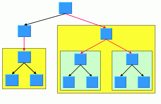
A graph that is a node in another graph is called a subgraph. Links that connect nodes of different subgraphs are called intergraph links. In
Leaf recursive tree, all red links are intergraph links and all black links are normal links. This is explained in detail in
Nested layouts.
The tree layout can treat a nested graph in specific situation at once and route the intergraph links as well as the normal links that belong to the tree. It can handle a leaf-recursive tree at once. A leaf recursive tree has the following properties:
it is a tree
only leaf nodes of the tree can contain nested graphs
the root node of the tree nested in a leaf node is connected by a link to the parent node of the leaf
Leaf recursive tree
Non leaf recursive tree
This graph is not a leaf recursive tree: the subgraphs are not nested in the leafs of the tree. The graph cannot be handled by the tree layout in recursive mode, but it can be handled by the hierarchical layout in recursive mode. If the graph is a leaf recursive tree and the layout mode is not the radial layout mode, the tree layout can handle the nested graph at once.
To enable the recursive mode:
In CSS
Specify in the GraphLayout section:
recursiveLeafLayoutMode: "true";
In Java
In Java™, use the method:
void setRecursiveLeafLayoutMode(boolean enable);
and call performLayout with the third parameter set to true as follows:
layout.performLayout(force, redraw, true);
The recursive leaf layout mode requires that all subtrees are laid out in the same style (for instance, they must all use the same flow direction). This is automatically the case when calling
layout.performLayout(force, redraw, true), and it is also the case when using CSS without specifying individual graph layouts per subgraph. If different layout styles are needed per subgraph, you must specify an individual layout per subgraph as described in
Individual layout styles per subgraph and in
Advanced recursion: mixing different layouts in a nested graph and in this case the recursive leaf layout mode cannot be used.
Setting layout parameters in recursive leaf layout mode by Java code
When you use CSS, the layout parameters are specified in CSS as usual, and the SDM engine handles the internal details automatically. However, if you want to specify layout parameters by code, in recursive leaf layout mode the tree layout is attached to the top level graph. Global layout parameters must be set on this layout instance. Layout parameters per node or per link must be set in the following way:
// link is directly contained in subgraph
IlvTreeLayout sublayout =
(IlvTreeLayout)topLevelLayout.getRecursiveLayout().getLayout(subgraph);
sublayout.setLinkStyle(link, IlvTreeLayout.ORTHOGONAL_STYLE);
This means that layout parameters per nodes and per links cannot be set on the top level layout, but on a sublayout retrieved via the
IlvRecursiveLayout from the top level layout.
For experts: additional tips for the TL
The tips and trick are relevant when accessing the layout instance directly in Java.
Most of the tips cannot be used when specifying CSS alone.
Specifying east-west neighbors
You can specify that two unrelated nodes must be direct neighbors in a direction perpendicular to the flow direction. In the level and radial layout modes, the nodes are placed in the same level next to each other. In the free layout and tip-over modes, the nodes are placed aligned at the north border. Such nodes are called
east-west neighbors because one node is placed as the direct neighbor on the east side of the other node. The other node becomes the direct neighbor on the west side of the first node. (See also
Using compass directions for positional layout parameters (TL)).
Technically, the nodes are treated as parent and child, even if there is no link between them. Therefore, one of the two nodes can have a real parent, but the other node must not because its virtual parent is its east-west neighbor.
The east-west neighbor feature can be used, for example, for annotating nodes in a typed syntax tree occurring in compiler construction.
Annotated syntax tree of statement a[25] = b[24] + 0.5; shows an example of such a tree.
Annotated syntax tree of statement a[25] = b[24] + 0.5;
In Java
To specify that two nodes are east-west neighbors, use the method:
void setEastWestNeighboring(Object eastNode, Object westNode);
You can also use the following method, which is identical except for the reversed parameter order:
void setWestEastNeighboring(Object westNode, Object eastNode);
If the flow direction is to the bottom, the latter method might be easier to remember because, in this case, west is to the left of east in the layout, which is similar to the text flow of the parameters.
To obtain the node that is the east or west neighbor of a node, use the calls:
Object getEastNeighbor(Object node);
Object getWestNeighbor(Object node);
Each node can have at most one east neighbor and one west neighbor because they are direct neighbors. If more than one direct neighbor is specified, it is partially ignored. Cyclic specifications can cause conflict as well. For instance, if node B is the east neighbor of node A and node C is the east neighbor of B, then node A cannot be the east neighbor of C. (Strictly speaking, such cycles could be technically possible in some situations in the radial layout mode, but nonetheless they are not allowed in any layout mode.)
If B is the east neighbor of A, then A is automatically the west neighbor of B. The east neighbor of A can itself have another east neighbor. You can thus create chains of east-west neighbors, which is a common way to visualize lists of trees. Two examples are shown in figure
Chains of east-west neighbors to visualize lists of trees.
Chains of east-west neighbors to visualize lists of trees
Retrieving link categories
The Tree Layout algorithm works on a spanning tree, as mentioned in a
The TL algorithm. If the graph to be laid out is not a pure tree, the algorithm ignores some links. To treat such links in a special way, you can obtain a list of nontree links.
Because there are parents and child nodes in the spanning tree, the following link categories must be distinguished:
A forward tree link is a link from a parent to its child.
A backward tree link is a link from a child to its parent. If the link is drawn as a directed arrow, the arrow points in the opposite direction to the flow direction.
A nontree link is a link between two unrelated nodes; neither one is a child of the other.
Link categories
The layout algorithm uses these link categories internally but does not store them permanently to save time and ensure memory efficiency. If you want to treat some link categories in a special way (for example, to call the Link Layout on the nontree links), you must specify before the layout that you want to access the link categories after the layout.
In Java
To do so, use the method
setCategorizingLinks in the following way:
layout.setCategorizingLinks(true);
// now perform a layout
layout.performLayout();
// now you can access the link categories
After the layout, the link categories can be obtained by the methods:
The link category data gets filled each time the layout is called, unless you set the method
setCategorizingLinks back to
false.
Sequences of layouts with incremental changes
You can work with trees that have become out-of-date, for example, the trees that need to be extended with more child nodes. If you perform a layout after an extension, you probably want to identify the parts that had already been laid out in the original graph. The Tree Layout algorithm supports these incremental changes in incremental mode because it takes the previous positions of the nodes into account. It preserves the relative order of the child nodes in the subsequent layout.
In nonincremental mode, the Tree Layout algorithm calculates the order of the child nodes from the node order given by the attached graph model (or grapher).
In this case, the layout is independent from the positions of the nodes before the layout. It does not preserve the relative order of the child nodes in subsequent layouts.
Incremental mode is enabled by default.
To disable incremental mode:
In CSS
Add to the GraphLayout section:
incrementalMode: "false";
In Java
Call:
layout.setIncrementalMode (false);
Interactive editing
The fact that the relative order of the layout is preserved is useful during interactive editing. It allows you to correct the layout easily. For instance, if the first layout places a node A left to its sibling node B but you need to reverse the order, you can simply move node A to the right of node B and start a new layout to clean up the drawing. In the second layout, A remains to the right of B, and the subtree of A “follows” node A.
Interactive editing to achieve a specific order of child nodes
Specifying the order of child nodes
Some applications require a specific relative order of the child nodes in the tree. This means that, for instance, when the flow direction is to the bottom, which child must be placed to the left of another child.
It can be achieved in non-incremental mode by specifying a node comparator as follows:
layout.setIncrementalMode(false);
layout.setNodeComparator(new Comparator() {
public int compare(Object o1, Object o2) {
... // compare two nodes
}
});
The comparator specifies the order as defined in the following table. For regular alignment, it results in increasing coordinates for the children. For tip-over alignment, it results in increasing distance from the parent. For balloon and radial modes, it results in clockwise orderings.
Layout Mode | Alignment | Flow Direction | Order |
Free, Level, Tip-over | no tip-over | Bottom | left to right |
Top | left to right |
Left | top to bottom |
Right | top to bottom |
Free, Level, Tip-over | tip-over | Bottom | top to bottom |
Top | bottom to top |
Left | right to left |
Right | left to right |
Radial, Balloon | any | any | clockwise |
Copyright © 2018, Rogue Wave Software, Inc. All Rights Reserved.