A connection port is the logical position
where a link is attached to a node. Normally, this position is
automatically determined by the link layout algorithm. Link
connection ports provide a way to modify this behavior by forcing
the links into a specific position that will be taken into account
by the graph layout algorithm.
By default, connection ports are not visible on a node. However,
you can display them by attaching to the view an interactor of type
IltMakeLinkInteractor operating in pin mode.
Connection ports can be either directed or
undirected. Links attached to a directed connection port originate
from a specific direction given by the port, and are drawn either
vertically or horizontally, depending on the direction. If the main
segment of the link is neither horizontal nor vertical, a short
segment is added to the extremity of the link to compensate for
this. This is the normal behavior implemented by the direct link
style of the link layout algorithm. On the other hand, links coming
from an undirected connection port can go in any direction, defined
randomly by the layout algorithm. In this case, no additional
segment is appended to their extremities.
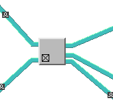
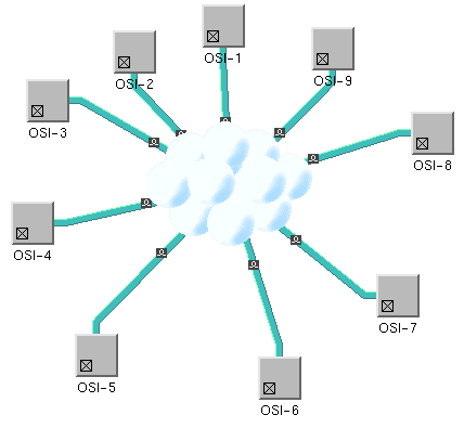
These two types of connection port are
illustrated in the following figures:

A node with four directed connection
ports

A node with an undirected link
connection port (at the center of the cloud)
A link connection port is defined by the
following:
- The point on the node where the link should end. This point is specified with two floating point values,
fxandfy, ranging between0and1. These are proportional values, relative to the link connection rectangle.NoteThe connection rectangle is generally represented by the bounding box of the node, except for groups for which this connection rectangle can be the group plinth.fx = 0corresponds to the left sidefx = 0.5corresponds to the vertical center linefx = 1corresponds to the right sidefy = 0corresponds to the top sidefy = 0.5corresponds to the horizontal center linefy = 1corresponds to the bottomNoteWhen there is more than one link, and the connection port is a directed one, the link bundling feature of the graph layout makes the link end in the vicinity of this point, not exactly on it.
- The direction of the outgoing link. For directed link connection ports, this direction is generally defined by IlvDirection. Top, IlvDirection. Bottom, IlvDirection. Left, and IlvDirection. Right, depending on which side of the node the link starts from. For undirected links, this value is IlvDirection. Center.
- Optionally, the distance between two links ending at the same link connection port. Negative values are ignored. This option is generally used to override the distance between two links set for the IltShortLinkLayout instance of a specific port.
When a link connection port is applied to a node, the target point
is computed from the values of
fx
,
fy
, and the link connection rectangle.
The class IltLinkPort is an enumeration type that
defines the following values:
Top
,
Bottom
,
Left
,
Right
, and
Center
. The first four values indicate that the link should connect to
the center point of the corresponding node side. For example,
Left
specifies that the link will be attached to the center of the left
side of the node. These values apply to directed link ports. The
last value,
Center
, applies to undirected link ports. These values can be customized
through CSS as illustrated in Customizing link port configuration in the Styling documentation. You can create your
own instances of IltLinkPort by providing specific values to
the
fx
,
fy
, and
direction
parameters.
Only the IltShortLinkLayout and IltLinkLayout (when set in short link mode)
layout algorithms implement link connection ports. When used in an
JViews TGO network
component, these layouts use the following optional information
through the IltDefaultNodeSideFilter that is installed
automatically:
- Each node can specify an array of pins as the
linksPortsproperty. If no array is defined, the following set of values is used by default:{IltLinkPort.Top,IltLinkPort.Bottom,IltLinkPort.Left,IltLinkPort.Right}.For information on how to configure link ports, refer to Customizing link port configuration in the Styling documentation. - Each link can specify the link port to which it will connect at both ends through the
fromPortandtoPortproperties. If no link port is defined, the layout algorithm will select one among those that are allowed.
How to create link connection ports
- Create an IltShortLinkLayout algorithm and attach it to the network component .
IltShortLinkLayout layout = new IltShortLinkLayout();
...
network.setLinkLayout(layout);
This layout algorithm allows you to handle link connection ports. You could also use IltLinkLayout. - Create new link connection ports using IltLinkPort.
...
IltLinkPort port1=
  new IltLinkPort("Right, above middle",1.0f,0.2f,1,0,-1);
Customizing the representation of links
For information on how to configure the link connection ports,
refer to Customizing link port configuration in the
Styling documentation.