As shown in the following figures, links can be represented in
various colors and line types, depending on the state they are in.
Links can show an icon representing their secondary state or have a
label. They can also be displayed with an information cluster
showing associated alarms. For a reference list of link states, see
Graphical representation of SONET primary
states and Graphical representation of SONET secondary
states.
These display modes apply to all kinds of link. Link
representations can also display the link physical medium (see Link
media), its networking technology (see Link
technology), its orientation (see Oriented
links), or whether this link is linked to itself (see Self-links).
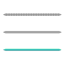
Links disabled, inactive, and active
states
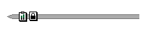
Link with status icons

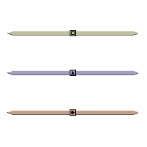
Link with label
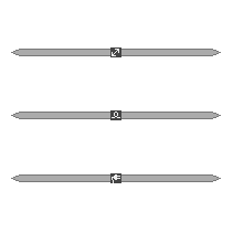
Links showing media attribute
Links showing technology attribute
Generally, the label appears at the center
of the link. When the link displays additional information, such as
the media icon or alarms, the label is moved either below that
information or to the right of it.
Link with alarm cluster
Link media
The link media is represented with an icon
that appears at its center. The following table lists the
predefined media icons.
Link media representation
Link
Media |
Represetation
|
Media
Name |
|---|---|---|
Communication
network |

|
CNET |
Fiber
|

|
Fiber
|
Electrical
|

|
Electrical
|
You can extend this small set of predefined link media using a
dedicated API, which is detailed in Customizing link media in the Styling documentation.
Link technology
The link technology is represented by an
icon in the center of the link, and a corresponding base color.
The following table lists the predefined technology icons and
colors.
Link technology representation
Link
Technology |
Representation
|
Technology
|
Technology
Name |
|---|---|---|---|
Circuit
switching |

|
Switching
|
CircuitSwitching
|
ATM/Frame
Relay |

|
Switching
|
ATM_FrameRelay
|
Wireless
Edge |

|
Edge |
WirelessEdge
|
IP |

|
IP |
IP |
SONET/SDH
|

|
Transport
|
SONET_SDH
|
DWDM
Optical |

|
Transport
|
DWDM_Optical
|
Multi
Layer |

|
Multiple
|
MultiLayer
|
Other
|

|
Unknown
|
Other
|
As this table implies, the default representation uses icons to
identify link technologies graphically and colors to group
similar technologies together. You can extend this small set of
predefined link technologies through the dedicated API or CSS,
see Customizing links. Note also that the link
technology color is overridden by the primary state color defined
by the link object state.
Oriented links
Oriented links provide a representation
for links with an arrow at one end or at both.
Link with an arrow
Link with two arrows
The presence or absence of arrows, as well as their graphical
characteristics are driven by dedicated CSS properties. (See
table CSS properties applying to arrows on link
base elements in the Styling documentation.)
By default, no arrow is displayed except in the case of links
that have an object state of type IltBiSONETObjectState. These links have
arrows at both ends with predefined graphical characteristics.
For a reference list of the common double SONET states, see Common pairs of SONET primary states .
Self-links
A self-link has both ends connected to the
same network element.

Self-link
In a self-link, the origin and the destination are the same. See
Link programming examples for an example on
how to create a self-link.
For information on how to customize the graphic representation of
links, refer to Customizing links.