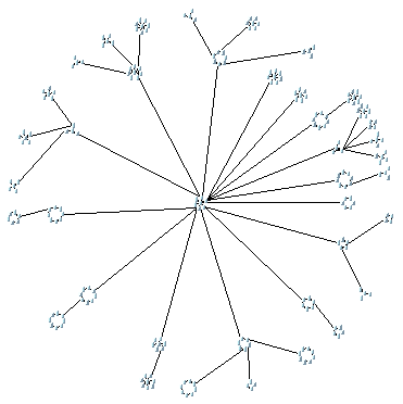
Circular layout (CL)
Describes the Circular Layout algorithm.

Gives samples of the Circular Layout (CL) and explains where it is used.

Lists the features and limitations of the Circular Layout (CL).

Describes the Circular Layout (CL) algorithm and gives samples.

Describes the generic features and parameters of Circular Layout.

Describes the parameters specific to Circular Layout.
General information about the CL
CL samples
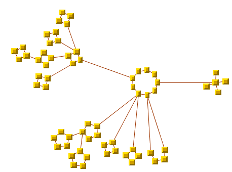
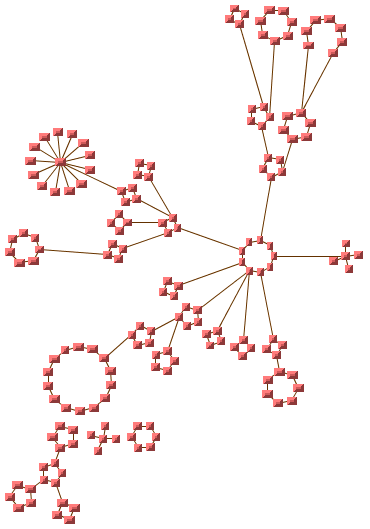
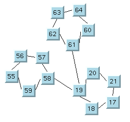
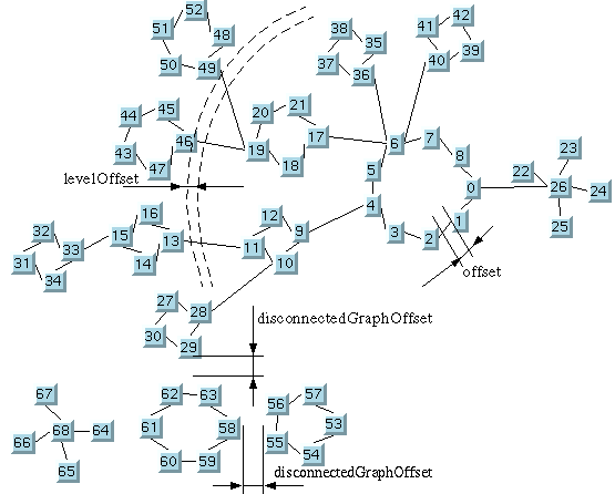
The following figures show sample drawings produced with the Circular Layout.
Ring-and-star topology drawing produced with the Circular Layout
Large ring-and-star topology drawing produced with the Circular Layout
What types of graphs suit the CL?

Graphs representing interconnected
ring and
star network topologies
Application domains for the CL
Application domains for the Circular Layout include:

Telecom and networking (LAN diagrams)

Business processing (organization charts)

Database and knowledge engineering (sociology, genealogy)

The World Wide Web (Web hyperlink neighborhood)
Features and limitations of the CL
Features

Displays network topologies composed of interconnected rings or stars.

Provides three clustering modes (see
Clustering mode (CL)). The first mode calculates the clusters automatically from the graph topology. The second mode requires a full specification of the clusters and the node orderings. The third mode assumes that the clusters are subgraphs whose initial position must be kept. The first and the third modes arrange the nodes of the cluster on circles by minimizing the link crossings, while the second mode keeps the specified node ordering. The first and the second mode place the clusters using a radial tree layout, while the third mode keeps the initial position of the clusters.

Takes into account the size of the nodes so that no overlapping occurs. (See also
The CL algorithm).
Limitations
Link crossings cannot always be avoided.
The CL algorithm
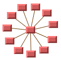
Ring and star topologies are similar in several ways. Look at
Ring topology and
Star topology to get an idea of their similarities.
Ring topology
Star topology
Both topologies are composed of nodes drawn in a circle. For the Circular Layout algorithm, the only difference between the ring and star topologies is that the star has a special node, called the star center, that is drawn at the center of the circle.
Depending on the clustering mode (see
Clustering mode (CL)), the layout allows you to specify the order of the nodes on the circle (see
Cluster membership and order of the nodes in a cluster (CL)) or it computes the order automatically such that the number of link crossings is small.
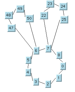
The network topology can be composed of more than one ring or star. These rings and stars can be partially interconnected; that is, two or more clusters can have a common node as shown in figure
Rings interconnected by common nodes. They can also be interconnected by links between nodes of two different clusters as shown in figure
Rings interconnected by links.
Rings interconnected by common nodes
Rings interconnected by links
The Circular Layout algorithm lays out ring and star topologies in a way that preserves the visual identity of each cluster and avoids overlapping nodes and clusters. See the sample drawings in
CL samples.
To understand how layout is performed in the clustering modes
AUTOMATIC and
BY_CLUSTER_IDS, consider a graph in which each node represents a ring or star cluster of a network topology. Add a link between two nodes each time there is an interconnection between the corresponding clusters. The Circular Layout algorithm is designed for the case where the graph obtained in this manner is a tree (that is, a graph with no cycles). If cycles exist, the layout is performed using a
spanning tree of the graph.
Starting from a root cluster (either a ring or a star), the clusters that are connected to the root cluster are drawn in a circle that is concentric to the root cluster. The radius of the circle is computed to avoid overlapping clusters. Next, the algorithm lays out the clusters connected to these last clusters on a larger circle, and so on. Each circle is called a level.
For networks that are not connected (that is, disconnected groups of clusters exist in the graph), more than one spanning tree exists. Each spanning tree is laid out separately and placed near the others. You can see it in the sample drawings in
CL samples.
In the clustering mode BY_SUBGRAPHS, each subgraph (cluster) keeps its initial position. The subgraphs can be placed either by a different layout algorithm or interactively.
Example of CL
In CSS
Below is a sample CSS specification using the Circular Layout algorithm. Since the Circular Layout places nodes and reshapes the links, it is usually not necessary to specify an additional link layout in CSS. The CSS specification can be loaded as a style file into an application that uses the
IlvDiagrammer class (see
Graph layout in Rogue Wave JViews Diagrammer).
SDM {
GraphLayout : "true";
LinkLayout : "false";
}
GraphLayout {
graphLayout : "Circular";
clusteringMode : "BY_CLUSTER_IDS";
offset : "20";
levelOffset : "30";
}
When using the clustering mode
BY_CLUSTER_IDS (see
Clustering mode (CL)), you need to specify the clustering information (see see
Cluster membership and order of the nodes in a cluster (CL)). When using the clustering mode
AUTOMATIC, you can optionally specify clustering information, but the algorithm tries to obtain missing cluster information automatically by analyzing the topology. When using the clustering mode
BY_SUBGRAPHS, each cluster must be a subgraph.
In Java
The following code sample uses the
IlvCircularLayout class. This code sample shows how to perform a Circular Layout on a grapher directly, without using a diagram component or any style sheet:
...
import ilog.views.*;
import ilog.views.graphlayout.*;
import ilog.views.graphlayout.circular.*;
...
IlvGrapher grapher = new IlvGrapher();
IlvManagerView view = new IlvManagerView(grapher);
IlvCircularLayout layout = new IlvCircularLayout();
layout.attach(grapher);
layout.setClusteringMode(IlvCircularLayout.BY_CLUSTER_IDS);
... /* Fill in the grapher with nodes and links here */
// create identifier for cluster 0
IlvClusterNumber clusterId = new IlvClusterNumber(0);
// specify the cluster identifier for cluster 0
// Assume there are three nodes: node1, node2, node3
// the ordering of the nodes: node1 -> node2 -> node3
layout.setClusterId(node1, clusterId, 0); // index 0
layout.setClusterId(node2, clusterId, 1); // index 1
layout.setClusterId(node3, clusterId, 2); // index 2
// create identifier for cluster 1
clusterId = new IlvClusterNumber(1);
// specify the cluster identifier for cluster 1
// Assume there are three nodes: node4, node5, node6
// the ordering of the nodes: node4 -> node5 -> node6
layout.setClusterId(node4, clusterId, 1); // index 1
layout.setClusterId(node5, clusterId, 2); // index 2
layout.setClusterId(node6, clusterId, 0); // index 0
try {
IlvGraphLayoutReport layoutReport = layout.performLayout();
int code = layoutReport.getCode();
System.out.println("Layout completed (" +
layoutReport.codeToString(code) + ")");
}
catch (IlvGraphLayoutException e) {
System.err.println(e.getMessage());
}
Generic features and parameters of the CL
The
IlvCircularLayout class supports the following parameters defined in the
IlvGraphLayout class. See
Base class parameters and features.
Extra feature for JViews Diagrammer:
The following comments describe the particular way in which these parameters are used by this subclass.
Layout of connected components (CL)
The layout algorithm can use the generic mechanism to lay out connected components. (For more information about this mechanism, see
Layout of connected components).
Layout region (CL)
This parameter has no effect if the clustering mode is BY_SUBGRAPHS.
It is not possible to allow the user to control the size of the layout by specifying a bounding box for the drawing. The layout algorithm chooses the size to have enough space to avoid overlapping nodes and clusters.
The layout region setting (either your own or the default setting) is used only to choose the position of the center of the drawing. This means that only the center of the layout region is considered. All three ways to specify the layout region are available for this subclass. See
Layout region.
Link clipping (CL)
The layout algorithm can use a link clip interface to clip the end points of a link. (See
Link clipping.)
This is useful if the nodes have a nonrectangular shape such as a triangle, rhombus, or circle. If no link clip interface is used, the links are normally connected to the bounding boxes of the nodes, not to the border of the node shapes. See
Using a link clipping interface with the Circular Layout for details of the link clipping mechanism.
Link connection box (CL)
The layout algorithm can use a link connection box interface to calculate the center of a node. See
Link connection box.
It is used when the option to connect links to node centers or link clipping is enabled.
It is only used if the link style is straight line. It is also used for self-links and multilinks, depending on the self-link or multilink mode.
Preserve fixed links (CL)
The layout algorithm does not reshape the links that are specified as fixed. (See
Preserve fixed links.)
Preserve fixed nodes (CL)
The layout algorithm does not move the nodes that are specified as fixed. (See
Preserve fixed nodes.)
Save parameters to named properties (CL)
The layout algorithm is able to save its layout parameters into named properties. This can be used to save layout parameters to
.ivl files. (For a detailed description of this feature, see
Save parameters to named properties and
Saving layout parameters and preferred layouts.)
Specific parameters of the CL
Describes the parameters specific to Circular Layout.

Describes the clustering mode parameters.

Lists the common parameters for modes AUTOMATIC and BY_CLUSTER_IDS.

Lists common parameters for all modes.

Lists the expert parameters for mode AUTOMATIC.

Lists the expert parameters for mode BY_CLUSTER_IDS.

Lists the expert parameters for mode BY_SUBGRAPHS.
Clustering mode (CL)
The Circular Layout algorithm has three clustering modes.
Example of selecting a clustering mode (CL algorithm)
To select a clustering mode:
In CSS
Add to the GraphLayout section:
clusteringMode : "BY_SUBGRAPHS";
In Java
Use the method:
void setClusteringMode(int mode);
The valid values for mode are:
 IlvCircularLayout.BY_CLUSTER_IDS
 (the default): Cluster identifiers need to be explicitly provided for each node (see
Cluster membership and order of the nodes in a cluster (CL)). The specified node ordering is preserved and no link crossing reduction is performed. A tree-like algorithm places the clusters.
 IlvCircularLayout.AUTOMATIC
: This mode is similar to the mode
BY_CLUSTER_IDS, but does not require any specification of clusters. The graph is divided into clusters by analyzing the topology of the graph. Biconnected components form initial clusters. The remaining nodes that do not belong to any (nontrivial) biconnected component form star clusters if their degree is larger than the star cluster threshold. Then, the initial clusters are merged, if they are smaller than the minimal size of a cluster, or split, if they are larger than the maximal size of a cluster. This mode arranges the nodes of each cluster so that the number of link crossings is small.
 IlvCircularLayout.BY_SUBGRAPHS
: The algorithm handles a nested graph, including intergraph links. It arranges the nodes of each subgraph in a circle, so that the number of link crossings is small. It respects the intergraph links and rotates the cluster so that the number of link crossings is small. It assumes that all nodes are nearly square and that all nodes are in subgraphs, but the subgraph nesting is only one level. Nodes that are inside subgraphs of subgraphs are not handled. In this mode, each subgraph keeps its initial position. The subgraphs can be placed either by a different layout algorithm or interactively.
Common parameters for modes AUTOMATIC and BY_CLUSTER_IDS
This section applies only if the clustering mode is set to AUTOMATIC or BY_CLUSTER_IDS. Both modes work in a similar way. The main difference is that the clustering mode AUTOMATIC can handle graphs where clusters are not or only partially specified; the clustering mode BY_CLUSTER_IDS requires a full specification of all clusters and throws an exception when performing a layout on a graph with incomplete cluster specification.
Cluster membership and order of the nodes in a cluster (CL)
Specifying clusters explicitly is not necessary in clustering mode BY_SUBGRAPHS, because the subgraphs form the clusters. In clustering mode AUTOMATIC, clusters can optionally be specified. In mode BY_CLUSTER_IDS, they must be specified before performing the layout.
Example of specifying node cluster (CL algorithm)
To specify to which cluster each node of the graph belongs:
In CSS
You must declare the clustering information in the node rules, like this:
node {
...
ClusterId : "@clusterIds";
StarCenter : "@starCenter";
}
where clusterIds refers to a node property whose value in the data model is given in the following syntax: <cluster-id>,<index>;<cluster-id>,<index>;... . Each cluster-id, index pair represents the identifier of the cluster and the ordering index of the node in this cluster. The index can be omitted. If only one pair is specified, this means the node belongs to only one cluster. If several pairs are specified for a node, this means that this node belongs to more than one cluster.
In the node rule above,
starCenter is a node property whose value in the data model must be either “true” of “false”. The nodes for which the value is “true” are considered “star centers” by the layout algorithm (see
Star clusters (CL)).
In Java
To specify the cluster membership, use a cluster identifier; that is, an instance of a subclass of the class
IlvClusterId (which is abstract). Two subclasses are provided:
You can combine these two types of identifiers as any other subclass of IlvClusterId. For example, you can write:
// create identifier for first cluster (integer)
IlvClusterNumber clusterId1 = new IlvClusterNumber(1);
// create identifier for second cluster (string)
IlvClusterNumber clusterId2 = new IlvClusterName("R&D network");
Then, if node1 to node3 belong to the first cluster, you can write:
layout.setClusterId(node1, clusterId1);
layout.setClusterId(node2, clusterId1);
layout.setClusterId(node3, clusterId1);
Assume that layout is an instance of IlvCircularLayout.
If you want the nodes to be drawn in a special order (for example, node1 -> node2 -> node3 ), you must also specify an index (an integer value) for each node:
layout.setClusterId(node1, clusterId1, 0);
layout.setClusterId(node2, clusterId1, 1);
layout.setClusterId(node3, clusterId1, 2);
Two methods allow you to specify the cluster to which a node belongs:
void setClusterId(Object node, IlvClusterId clusterId)
void addClusterId(Object node, IlvClusterId clusterId)
If you call the first method, the node belongs only to the cluster whose identifier is clusterId. The second method allows you to specify that a node belongs to more than one cluster.
These methods have another version with an additional argument, an integer value representing the index:
void setClusterId(Object node, IlvClusterId clusterId, int index)
void addClusterId(Object node, IlvClusterId clusterId, int index)
This value is used to order the nodes on the cluster. If you specify these indices, the algorithm sorts the nodes in ascending order according to the index values.
The values of the index cannot be negative. They do not need to be continuous; only the order of the values is important.
To obtain the specified index of a node in a given cluster, use the method:
int getIndex(Object node, IlvClusterId clusterId)
If no index is specified for the node, the method returns the value IlvCircularLayout.NO_INDEX. It is a negative value.
To obtain an enumeration of the cluster identifiers for the clusters to which the node belongs, use the method:
Enumeration getClusterIds(Object node)
The elements of the enumeration are instances of a subclass of IlvClusterId.
To efficiently obtain the number of clusters to which a node belongs, use the method:
int getClusterIdsCount(Object node)
To remove a node from the cluster with the specified identifier, use the method:
void removeClusterId(Object node, IlvClusterId clusterId)
To remove a node from all the clusters to which it belongs, use the method:
void removeAllClusterIds(Object node)
Root clusters (CL)
The algorithm arranges the clusters of each
connected component of the graph of clusters around a “root cluster”. By default, the algorithm can choose this cluster. Optionally, you can specify one or more root clusters (one for each connected component).
Example of specifying root clusters (CL algorithm)
To specify one or more root clusters (one for each connected component):
In CSS
It is not possible to specify root clusters in CSS.
In Java
Use the method:
void setRootClusterId(IlvClusterId clusterId)
To obtain an enumeration of the identifiers of the clusters that have been specified as root clusters, use the method:
Enumeration getRootClusterIds()
This parameter has no effect if the clustering mode is BY_SUBGRAPHS.
Star clusters (CL)
Example of specifying star center (CL algorithm)
To specify whether a node is the center of a star:
In CSS
Add to the GraphLayout section:
starCenter : "true";
In Java
Use the method:
void setStarCenter(Object node, boolean starCenter)
To know whether a node is the center of a star, use the method:
boolean isStarCenter(Object node)
By default, a node is not the center of a star.
This parameter has no effect if the clustering mode is BY_SUBGRAPHS.
Get the contents, the position, and the size of the clusters (CL)
At times, you might need to know the position and the size of the circle on which the nodes for each cluster are drawn. It may be the case if you want to perform some reshaping operations on the links. To do so, you can obtain a vector containing all the cluster identifiers after the layout is performed. In clustering mode AUTOMATIC, the vector can contain generated cluster identifiers if no clusters were specified.
Example of obtaining a vector that contains all the cluster identifiers (CL algorithm)
To obtain a vector containing all the cluster identifiers after the layout is performed:
In CSS
It is not possible to get the contents, position, or size of the clusters via CSS.
To obtain a vector containing all the cluster identifiers after the layout is performed:
In Java
Use the method:
Vector getClusterIds()
The vector contains instances of a subclass of IlvClusterId. By browsing the elements of this Vector, you can get the necessary information for each cluster:
float getClusterRadius(int clusterIndex)
IlvPoint getClusterCenter(int clusterIndex)
Vector getClusterNodes(int clusterIndex)
The getClusterNodes method returns the nodes that make up the cluster. The argument clusterIndex represents the position of the cluster in the Vector returned by the method getClusterIds().
Do not use these methods if the clustering mode is BY_SUBGRAPHS.
Dimensional parameters (CL)
This section illustrates the dimensional parameters used in the Circular Layout algorithm. These parameters are explained in the sections that follow.
The clustering mode
BY_CLUSTER_IDS also works with a disconnected graph offset. It is explained in the section
Handling of disconnected graphs.
Dimensional parameters for the Circular Layout algorithm
Offset (CL)
The layout algorithm tries to preserve a minimum distance between nodes (see figure
Dimensional parameters for the Circular Layout algorithm).
Example of specifying the offset (CL algorithm)
To specify the offset:
In CSS
Add to the GraphLayout section:
offset: "20.0";
In Java
Use the method:
void setOffset(float offset)
Level offset (CL)
If the clustering mode is BY_SUBGRAPHS, the level offset parameter controls the minimal offset between nodes that belong to the same cluster.
If the clustering mode is BY_CLUSTER_IDS, the following scenario applies.
As explained in
The CL algorithm, interconnected rings and clusters are drawn on concentric circles around a root cluster. The radius of each concentric circle is computed to avoid overlapping clusters. In some cases, you might want to increase this radius to obtain a clearer drawing of the network. To meet this purpose, the radius is systematically increased with a “level offset” value (see figure
Dimensional parameters for the Circular Layout algorithm).
Example of specifying the level offset (CL algorithm)
To specify the level offset:
In CSS
Add to the GraphLayout section:
levelOffset : "30.0";
In Java
Use the method:
void setLevelOffset(float offset)
The default value is zero.
This parameter has no effect if the clustering mode is BY_SUBGRAPHS.
Common parameters for all modes
The following layout parameters work for all clustering modes.
Link style (CL)
When the layout algorithm moves the nodes,
straight-line links, such as instances of
IlvLinkImage, automatically “follow” the new positions of their end nodes. If the grapher contains other types of links (for example,
IlvPolylineLinkImage or
IlvSplineLinkImage), the shape of the link might not be appropriate because the intermediate points of the link is not moved. In this case, you can ask the layout algorithm to automatically remove all the intermediate points of the links (if any).
Example of specifying automatic removal of all intermediate points of the links (CL algorithm)
To specify that the layout algorithm automatically removes all the intermediate points of the links (if any):
In CSS
Add to the GraphLayout section:
linkStyle : "STRAIGHT_LINE_STYLE";
In Java
Use the method:
void setLinkStyle(int style)
The valid values for style are:
 IlvCircularLayout.NO_RESHAPE_STYLE
None of the links is reshaped in any way.
 IlvCircularLayout.STRAIGHT_LINE_STYLE
All the intermediate points of the links (if any) are removed. It is the default value.
Connect links to node center (CL)
This feature is shared by all subclasses of the Basic Link Style Layout. See
Connect links to node center for details.
Multilink and self-link features (CL)
These features are shared by all subclasses of the Basic Link Style Layout. See
Multilink and self-link features for details.
Using a link clipping interface with the Circular Layout
By default, the Circular Layout does not place the connection points of links. It relies on the link connectors of the nodes to determine the connection points. If no link connectors are installed at the nodes, the default behavior is to connect to a point at the border of the bounding box of the nodes.
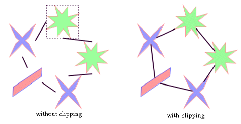
If the node has a shape other than rectangular, such as a triangle, rhombus, or circle, you may want the connection points to be placed exactly on the border of the shape. This can be achieved by specifying a link clip interface. The link clip interface allows you to correct the calculated connection point so that it lies on the border of the shape.
The following figure shows an example of link clipping.
Effect of link clipping interface
You can modify the position of the connection points of the links by providing a class that implements the
IlvLinkClipInterface. An example for the implementation of a link clip interface is in
Link clipping.
Example of setting a link clip interface (CL algorithm)
To set a link clip interface:
In Java
Use the method:
void setLinkClipInterface(IlvLinkClipInterface interface)
NOTE The link clip interface requires link connectors at the nodes of an
IlvGrapher that allow connector pins to be placed freely at the node border. It is recommended that you use
IlvFreeLinkConnector or
IlvClippingLinkConnector for link connectors to be used in combination with
IlvGrapher objects. The clip link connector updates the clipped connection points automatically during interactive node movements.
Expert parameters for mode AUTOMATIC
The clustering mode AUTOMATIC can calculate clusters and order the nodes within clusters to avoid link crossings. By default, it places the clusters relative to each other with a tree layout ( IlvTreeLayout ) in radial mode. You can also specify other layouts to handle the cluster placement. The following parameters work only in clustering mode AUTOMATIC.
Fine-tuning the clustering
The clustering mode AUTOMATIC takes the specified clusters as initial clusters into account. If some or all nodes have no specified cluster, it calculates clusters from the topology of the graph.
This mode takes several topology criteria into account:

Biconnectivity

Minimum number of nodes per cluster

Maximum number of nodes per cluster

High degree nodes to form star clusters
Clustering by biconnectivity
If a set of nodes has many connections among each other, they must form a cluster. The informal property "many connections" can be mathematically described by the term biconnectivity: A set of nodes is biconnected if removing only one node or only one link keeps the nodes connected. For example, a connection ring is always biconnected. It is a suitable criterion for clusters. The algorithm detects by default first the biconnected parts of the graph, and forms a regular cluster (not a star cluster) for each part. If it is not suitable, the detection of biconnected components can also be disabled.
Example of disabling the detection of biconnected parts (CL algorithm)
To disable the detection of biconnected components:
In CSS
Add to the GraphLayout section:
clusterByBiconnectivity: "false";
In Java
Use the method:
void setClusterByBiconnectivity(boolean enable)
This parameter has no effect if the clustering mode is BY_CLUSTER_IDS or BY_SUBGRAPHS.
Minimum cluster size
It is possible to specify the minimal size of regular clusters (not of star clusters). If the initial clusters are too small, they are merged into larger clusters.
Example of specifying the minimum cluster size (CL algorithm)
To specify the minimum cluster size:
In CSS
Add to the GraphLayout section:
minimumClusterSize: "10";
In Java
Use the method:
void setMinimumClusterSize(int size)
This parameter has no effect if the clustering mode is BY_CLUSTER_IDS or BY_SUBGRAPHS.
Maximum cluster size
It is possible to specify the maximal size of regular clusters (not of star clusters). If the initial clusters are too large, they are split into smaller clusters. This value is only a hint. If the minimum cluster size and the maximum cluster size are close to each other, the maximum cluster size cannot always be respected.
Example of specifying the maximum cluster size (CL algorithm)
To specify the maximum cluster size:
In CSS
Add to the GraphLayout section:
maximumClusterSize: "30";
In Java
Use the method:
void setMaximumClusterSize(int size)
Splitting clusters is an iterative process. It is possible to specify the maximum number of iterations to obtain the maximum cluster size; the more iterations, the better the quality, and the slower the layout.
Example of specifying the maximum number of max cluster iterations (CL algorithm)
To specify the maximum number of iterations:
In CSS
Add to the GraphLayout section:
maximumNumberOfIterationsToReachMaxClusterSize: "15";
In Java
Use the method:
void setMaximumNumberOfIterationsToReachMaxClusterSize(int numIterations)
These parameters have no effect if the clustering mode is BY_CLUSTER_IDS or BY_SUBGRAPHS.
Minimum star cluster size
Besides regular clusters, the layout algorithm can also detect star clusters. It detects nodes with high degree that have many unclustered neighbors and forms them into clusters with the high degree node as star center
Example of specifying the minimum star cluster size (CL algorithm)
To specify the minimum degree to form a node and its neighbor to a star cluster:
In CSS
Add to the GraphLayout section:
highDegreeStarClusterSize: "10";
In Java
Use the method:
void setHighDegreeStarClusterSize(int size)
This parameter has no effect if the clustering mode is BY_CLUSTER_IDS or BY_SUBGRAPHS.
Fine-tuning the crossing reduction
If the ordering of the nodes within each cluster is not specified by cluster indices (see
Cluster membership and order of the nodes in a cluster (CL)), then the
AUTOMATIC mode reorders the nodes within each cluster to avoid link crossings. It is only a heuristic and cannot always guarantee the minimum number of link crossings. There are two types of links: intracluster links connect nodes that belong to the same cluster, and intercluster links connect nodes of different clusters. During the crossing reduction, intracluster links compete with intercluster links. Some node orderings of a cluster produce more crossings of links inside the cluster, while other node orderings produce more crossings of links connecting different clusters. The behavior can be controlled by crossing weights.
Intercluster link crossing reduction
The crossing reduction step that considers intercluster links is the slowest part of the crossing reduction. It is enabled by default, but it can be disabled. If disabled, only intracluster links are considered to calculate the ordering of nodes within each cluster.
Example of disabling intercluster link crossing reduction (CL algorithm)
To disable the intercluster link crossing reduction:
In CSS
Add to the GraphLayout section:
interClusterCrossingReduction: "false";
In Java
Use the method:
void setInterClusterCrossingReduction(boolean enable)
This parameter has no effect if the clustering mode is BY_CLUSTER_IDS or BY_SUBGRAPHS.
Intracluster link crossing penalty
The crossing reduction tries to minimize the sum of penalties of crossings. If two intracluster links cross, it contributes to the sum with the intracluster penalty. Increase this penalty if intracluster links must have a higher weight when calculating the node ordering for each cluster.
Example of specifying the intracluster penalty (CL algorithm)
To specify the intracluster link crossing penalty:
In CSS
Add to the GraphLayout section:
intraClusterLinkCrossingPenalty: "2.0";
In Java
Use the method:
void setIntraClusterLinkCrossingPenalty(float penalty)
This parameter has no effect if the clustering mode is BY_CLUSTER_IDS or BY_SUBGRAPHS.
Intercluster link crossing penalty
If two intercluster links cross, it contributes to the penalty sum with the intercluster penalty. Increase this penalty if intercluster links must have a higher weight when calculating the node ordering for each cluster.
Example of specifying the intercluster penalty (CL algorithm)
To specify the intercluster link crossing penalty:
In CSS
Add to the GraphLayout section:
interClusterLinkCrossingPenalty: "2.0";
In Java
Use the method:
void setInterClusterLinkCrossingPenalty(float penalty)
This parameter has no effect if the clustering mode is BY_CLUSTER_IDS or BY_SUBGRAPHS.
Mixed cluster link crossing penalty
If an intracluster link crosses an intercluster link, it contributes to the penalty sum with the mixed cluster penalty.
Example of specifying the mixed cluster penalty (CL algorithm)
To specify the mixed cluster link crossing penalty:
In CSS
Add to the GraphLayout section:
mixedClusterLinkCrossingPenalty: "2.0";
In Java
Use the method:
void setMixedClusterLinkCrossingPenalty(float penalty)
This parameter has no effect if the clustering mode is BY_CLUSTER_IDS or BY_SUBGRAPHS.
Layout of cluster graph
The nodes of each cluster are placed in a circle. Then each circle is placed in the plane. The circular layout uses by default a tree layout in radial mode to place the circles.
Example of handling layout of cluster graphs
The layout parameters of the tree layout can be changed by accessing the tree layout:
In Java
To access the layout of the cluster graph, use the method:
IlvGraphLayout getLayoutOfClusterGraph()
By default, the layout is an instance of IlvTreeLayout. You can set any global tree layout parameter on this layout instance.
You can also specify a different layout instance to place the clusters:
In CSS
Add to the GraphLayout section:
layoutOfClusterGraph: "@#MyLayout";
and a new rule that specifies the details of MyLayout, for instance:
Subobject#MyLayout {
class : "ilog.views.graphlayout.uniformlengthedges.IlvUniformLengthEdgesLayout";
respectNodeSizes : "true";
}
In Java
Use the method:
void setLayoutOfClusterGraph(IlvGraphLayout layout)
Handling of disconnected graphs
The layout algorithm can use the generic mechanism to lay out connected components. (For more information about this mechanism, see
Layout of connected components). This generic mechanism is available at the circular layout instance itself, but as well at the tree layout instance that lays out the cluster graph.
Example of handling of disconnected graphs
You can enable it on the circular layout itself:
In CSS
Add to the GraphLayout section:
layoutOfConnectedComponentsEnabled: "true";
layoutOfConnectedComponents: "@#SomeGridLayout";
In Java
Call on the circular layout instance:
circularLayout.setLayoutOfConnectedComponentsEnabled(true);
circularLayout.setLayoutOfCOnnectedComponents(someGridLayout);
If it is disabled on the circular layout, the layout of the cluster graph handles disconnected components. You can enable the generic handling of disconnected components as well on the layout of the cluster graph (if it is supported there, which is true for the default tree layout) via
In Java
circularLayout.getLayoutOfClusterGraph().setLayoutOfConnectedComponentsEnabled(true);
circularLayout.getLayoutOfClusterGraph().setLayoutOfCOnnectedComponents(someGridLayout);
but it has the same effect as if you specify it directly on the circular layout instance.
Expert parameters for mode BY_CLUSTER_IDS
The clustering mode BY_CLUSTER_IDS uses a built-in radial tree layout that does not provide the full functionality of the IlvTreeLayout used in clustering mode AUTOMATIC. It is simple and tuned for speed. However, it has some useful expert parameters.
Area minimization (CL)
For large graphs, the radius of the concentric circles on which the clusters are placed can become very large. Therefore, the Circular Layout provides an optional mode that reduces the total area of the layout. To reduce the total area, the clusters are distributed more equally on the circle.
Example of specifying area minimization mode (CL algorithm)
To enable or disable the area minimization mode:
In CSS
Add to the GraphLayout section:
areaMinimizationEnabled: "true";
In Java
Use the method:
void setAreaMinimizationEnabled(boolean option)
The default value is false (area minimization is disabled).
Deciding whether to enable the area minimization mode essentially depends on the size of the network; the area minimization mode is most suitable for large networks.
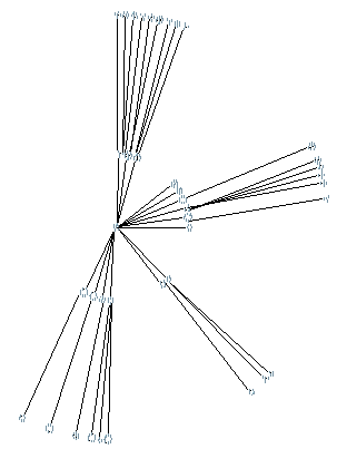
To get an idea of the difference that area minimization mode makes, compare the following layouts of the same network.
Area minimization disabled (default)
Area minimization enabled
This parameter has no effect if the clustering mode is AUTOMATIC or BY_SUBGRAPHS.
Handling of disconnected graphs
As explained in the CL Algorithm, each connected component of the network is laid out separately. When the clustering mode
BY_CLUSTER_IDS is enabled, there are two ways to arrange the components. The one way is using the generic mechanism to lay out connected components that places the components using a grid layout. In this case, layout parameters concerning component distances must be set on the grid layout. For more information about this mechanism, see
Layout of connected components (CL).
The other way is using the built-in radial tree layout directly. It arranges the components within the specified layout region. In this case, the minimum offset between two components can be specified in the following way (see
Dimensional parameters (CL)).
Example of specifying the offset between each connected component (CL algorithm)
To specify the offset between each connected component:
In CSS
Add to the GraphLayout section:
disconnectedGraphOffset: "2.5";
In Java
Use the method:
void setDisconnectedGraphOffset(float offset)
This parameter has no effect if the clustering mode is BY_SUBGRAPHS.
Expert parameters for mode BY_SUBGRAPHS
The clustering mode
BY_SUBGRAPHS arranges the nodes of each subgraph in a circle but keeps the position of each subgraph fixed. It works only if the generic mechanism to lay out connected components is disabled. See
Layout of connected components. It orders the nodes along the circle to avoid link crossings.
Node offset
The layout algorithm tries to preserve a minimum distance between nodes of the same cluster or subgraph.
Example of specifying the offset (CL algorithm)
To specify the offset:
In CSS
Add to the GraphLayout section:
offset: "20.0";
In Java
Use the method:
void setOffset(float offset)
Maximum number of permutations
The layout algorithm orders the nodes along the circle to avoid link crossings. To do so, it tries various permutations of the nodes of each cluster and keeps the best one; the more permutations tried, the slower the layout algorithm, but also the higher the quality of the result.
Example of specifying the maximum number of permutations (CL algorithm)
To specify the maximum number of permutations:
In CSS
Add to the GraphLayout section:
maxNumberOfPermutations: "15";
In Java
Use the method:
void setMaxNumberOfPermutations(int numberOfPermutations)
This parameter has no effect if the clustering mode is AUTOMATIC or BY_CLUSTER_IDS.
Copyright © 2018, Rogue Wave Software, Inc. All Rights Reserved.
