Common features of layouts that are subclasses of Basic Link Style Layout
Describes features that are shared by some of the layouts only; these layouts are subclasses of the class that supports the Basic Link Style Layout.

Lists the algorithms that are subclasses of the Basic Link Style Layout.
Describes the parameter
connectLinksToNodeCenters of the subclasses of the Basic Link Style Layout and when it is appropriate to use it.
Describes multilink and self-link features, which are supported by subclasses of Basic Link Style Layout only.
Layout algorithms that are subclasses of Basic Link Style Layout
The following algorithms are subclasses of Basic Link Style Layout:
Topological Mesh Layout
Uniform Length Edges
Random Layout
Circular Layout
Each of these algorithms supports the features documented in this section in the same way. For the purposes of examples, Uniform Length Edges Layout is used to show how these algorithms provide this support.
Connect links to node center
If the link style is STRAIGHT_LINE_STYLE, the layout can connect the links so that they point to the node center.
Connecting the links so that they point to the node center is particularly useful when the nodes use an instance of
IlvFreeLinkConnector or
IlvClippingLinkConnector and no link clip interface is set.
Example of specifying links that connect to node center
In CSS
To specify that links connect to node centers, add to the GraphLayout section:
connectLinksToNodeCenters: "true";
In Java
To specify that links connect to node centers use the method:
void setConnectLinksToNodeCenters(boolean enable)
Multilink and self-link features
Describes multilink and self-link features, which are supported by subclasses of Basic Link Style Layout only.
Describes how to route multilinks.
Describes the behavior of self-links and how to handle them.
Describes how to set the spacing for self-links and how to specify a relative or absolute attach position.
Describes how to set the distribution of multiple self-links and how to handle the offset between the bends of the self-links.
Multiple links between the same pair of nodes
Sometimes a graph has multiple links between the same pair of nodes. When these links are routed straight and use the same connection point at the nodes, they overlap and cannot be distinguished. To avoid such overlaps, the specified layouts have a multilink mode that is applied only when the link style is set to STRAIGHT_LINE_STYLE. This mode has no effect when the link style is NO_RESHAPE_STYLE.
Example of specifying how multiple links are routed
In CSS
To specify the multilink mode, add to the GraphLayout section:
multiLinkMode: "NARROW_STRAIGHT_LINE_BUNDLE";
In Java
To specify the multilink mode, use the method:
void setMultiLinkMode(int mode)
The valid values for mode are given with the example of Uniform Length Edges layout:
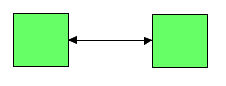
IlvUniformLengthEdgesLayout.NO_BUNDLE: Multiple links between the same pair of nodes are not treated in any special way. They are not spread out and might overlap.
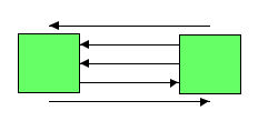
IlvUniformLengthEdgesLayout.STRAIGHT_LINE_BUNDLE: Multiple links between the same pair of nodes are routed as straight lines, but shifted relative to each other to avoid overlaps. Contrary to the narrow mode, the shift offset is not limited by the node size.
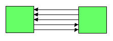
IlvUniformLengthEdgesLayout.NARROW_STRAIGHT_LINE_BUNDLE: Similar to the straight line bundle mode, but the shift offset is limited by the size of the two end nodes of the link bundle and therefore can appear narrower. When you have too many multiple links between the same pair of nodes, this mode avoids shifting the links so far away that they no longer appear connected to the nodes. This mode is the default.
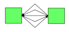
IlvUniformLengthEdgesLayout.CONNECTED_ONE_BEND_BUNDLE: Multiple links between the same pair of nodes are routed with one bend to avoid overlaps. All links in the bundle start at the same connection point and end at the same connection point.
IlvUniformLengthEdgesLayout.FREE_ONE_BEND_BUNDLE: Multiple links between the same pair of nodes are routed with one bend to avoid overlaps. Contrary to the connected one bend bundle mode, the link connection point is not enforced; that is, the node and link are free to place the connection point. There is no guarantee that all links of the bundle start or end at a common point.
The FREE_ONE_BEND_BUNDLE mode is particularly useful when:
An
IlvCenterLinkConnector or
IlvPinLinkConnector is used that cannot change the connection point.
An
IlvClippingLinkConnector is used while the layout should not change the attachment point.
If the multilink mode is not NO_BUNDLE, the offset between the shifted links or between the bends of the links respectively can be specified:
In CSS
Add to the GraphLayout section:
multiLinkOffset: "10";
multiLinkMaxSpread: "60";
In Java
Use the methods:
setMultiLinkOffset(float offset);
setMultiLinkMaxSpread(float maxSpread);
The multilink offset is the offset between two neighboring links (or their bends). The value of maxSpread limits this offset to avoid having too much space used when you have too many multiple links. If the multilink offset is 10 and the value of maxSpread is 60, the effective offset is 10 if you have less than six multilinks. If you have more multilinks, the effective offset is reduced. For example, if you have 15 multilinks, the effective offset will be 4 instead of 10 to ensure that the links are shifted at most 60 units apart from each other. If the multilink mode is NARROW_STRAIGHT_LINE_BUNDLE, the effective offset is further limited by the size of the bounding box of both end nodes of a link bundle.
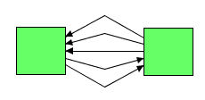
Examples of use of mode and offset | Graphical result |
NO_BUNDLE | |
STRAIGHT_LINE_BUNDLE when the value of maxSpread is set too high. | |
NARROW_STRAIGHT_LINE_BUNDLE: the same result can be obtained with STRAIGHT_LINE_BUNDLE by reducing the value of maxSpread. | |
CONNECTED_ONE_BEND_BUNDLE | |
FREE_ONE_BEND_BUNDLE when the links are initially attached to node centers. The same result can be obtained with CONNECTED_ONE_BEND_BUNDLE in combination with the expert option connectLinksToNodeCenters. For example, see IlvBasicLinkStyleLayout.setConnectLinksToNodeCenters(boolean) | |
Self-links that start and end at the same node
Self-links are links that start and end at the same node. They can even occur as multiple links, when they are called multiself-link bundle. When links are routed straight, self-links are not visible, because they start and end at the same point in the center of the node. To avoid this effect, the layouts listed in
Layout algorithms that are subclasses of Basic Link Style Layout have a self-link mode that is applied only when the link style is set to
STRAIGHT_LINE_STYLE. In spite of the name of the link style, the combination of mode and style causes bends to be added to the self-links to make them visible. When the link style is
NO_RESHAPE_STYLE, self-link mode has no effect.
Example of specifying how self-links are routed
In CSS
To specify self-link mode, add to the GraphLayout section:
selfLinkMode: "NARROW_CONNECTED_SQUARE";
To specify self-link mode, use the method:
void setSelfLinkMode(int mode)
The valid values for mode are given with the example of Uniform Length Edges layout:
IlvUniformLengthEdges.NO_BENDS: Self-links are not reshaped with bends and might not be visible.
IlvUniformLengthEdges.CONNECTED_RECTANGULAR.
IlvUniformLengthEdges.FREE_RECTANGULAR.
IlvUniformLengthEdges.CONNECTED_SQUARE.
IlvUniformLengthEdges.FREE_SQUARE.
IlvUniformLengthEdges.NARROW_CONNECTED_RECTANGULAR: This mode is the default.
IlvUniformLengthEdges.NARROW_FREE_RECTANGULAR.
IlvUniformLengthEdges.NARROW_CONNECTED_SQUARE.
IlvUniformLengthEdges.NARROW_FREE_SQUARE.
All these modes, except the no-bends mode, create three bends placed orthogonally, so that the segments approximately resemble three-quarters of a rectangle or of a square, the fourth quarter being the node where the self-link is attached. Depending on the node dimension, the rectangular modes create four-cornered shapes that are not squares; the square modes create squares. The square modes are useful for spline self-links in particular, because the spline can then approximately resemble three-quarters of a circle.
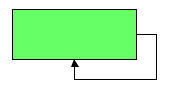
Mode | Graphical result |
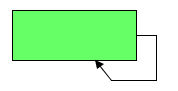
CONNECTED_RECTANGULAR mode | |
CONNECTED_SQUARE mode | |
CONNECTED_SQUARE mode with spline link | |
The connected modes place the connection points at the border of the node. The free modes place the bends at the same position as the corresponding connected modes, but the link connection point is not enforced; that is, the node and link are free to select where to place the connection point. The link segments in the free modes might not be orthogonal, because the connection point is not enforced.
The free modes are particularly useful when an IlvCenterLinkConnector or IlvPinLinkConnector is used that cannot change the connection point.
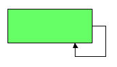
Mode | Graphical result |
CONNECTED_SQUARE mode | |
FREE_SQUARE mode with link clip connector | |
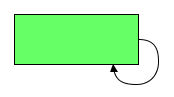
The narrow modes and the other modes behave the same for single self-links. If you have multiple self-links at the same node, the self-links are shifted by an offset to avoid overlaps. In this case, the narrow modes differ from the other modes; the multiself-link bundle may appear narrower, because the shift offset of the multiple self-links is limited by the size of the end node.
Examples of use of mode and offset | Graphical result |
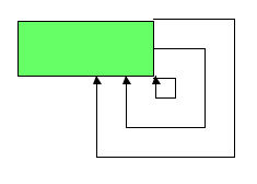
CONNECTED_SQUARE mode | |
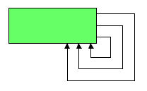
NARROW_CONNECTED_SQUARE mode | |
Self-links can occur at all four corners of the node. The algorithm determines automatically which corner is most appropriate, depending on the direction of all other links. You can restrict which corner should be used.
In CSS
Add to the GraphLayout section:
selfLinkAllowedCorners: "TopLeft BottomLeft TopRight";
The allowed corners must be a space-separated list from TopLeft, BottomLeft, TopRight, and BottomRight. If one of these options is not specified, all corners are allowed.
In Java
Use the method:
setSelfLinkAllowedCorners(int corners);
The allowed corners are a bitwise OR combination chosen from the following constants; for example, in Uniform Length Edges layout, IlvUnifiedLengthEdgesLayout.TOP_LEFT, IlvUnifiedLengthEdgesLayout.BOTTOM_LEFT, IlvUnifiedLengthEdgesLayout.TOP_RIGHT, and IlvUnifiedLengthEdgesLayout.BOTTOM_RIGHT.
By default, self-links are oriented clockwise. You can specify other orientations.
In CSS
Add to the GraphLayoutsection:
selfLinkOrientation: “COUNTER_CLOCK_WISE”;
In Java
Use the method:
setSelfLinkOrientation(int orientation);
Using IlvUniformLengthEdgesLayout as an example, the valid values for orientation are:
IlvUniformLengthEdgesLayout.CLOCK_WISE IlvUniformLengthEdgesLayout.COUNTER_CLOCK_WISE IlvUniformLengthEdgesLayout.HORIZONTAL_TO_VERTICAL Self-links start with a horizontal segment and end with a vertical segment.
IlvUniformLengthEdgesLayout.VERTICAL_TO_HORIZONTAL Self-links start with a vertical segment and end with a horizontal segment.
Self-links: spacing parameters
The spacing between the node bounds and the self-link bends can be specified. If a positive value is specified, this value is used to define the spacing. If a negative value is specified, the spacing is calculated automatically. The behavior with negative values is particularly useful for the square self-link modes in combination with spline links to form approximate circle shapes for self-links.
In CSS
Add to the GraphLayout section:
selfLinkSpacing: “10”;
In Java
Use the method:
setSelfLinkSpacing(float spacing);
You can specify the position where the self-link attaches at the bounding box of the node. If the self-link mode is a rectangular mode, the attach position can be specified at both border sides where the self-link attaches. For example, a self-link at the lower right corner attaches at the lower border side of the node, which can be specified as x-component, and at the right border side of the node, which can be specified as y-component. If the self-link mode is a square mode, it takes into account only the attach position at one of the two sides, because the shape must be a square, so the other attach position is automatically calculated.
For experts: If you specify both an x-attach position and a y-attach position when the self-link mode is a square mode, the algorithm always chooses the value that results in a smaller square size.
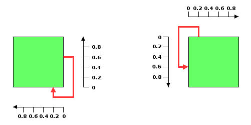
The attach position is always specified relative to the corner where the self-link occurs. The coordinate 0 is exactly at the corner and increasing values move the attach position farther from the corner. Therefore, the rectangular or square shape of the self-link grows ever larger with increasing values. For example, when the self-link is at the lower right corner, increasing x-components moves the attach position toward the left, and increasing y-components moves it toward the upper corner. When the self-link is at the upper left corner, increasing x-components moves the attach position toward the right, and increasing y-components moves it toward the lower corner. The attach position can be specified relative to the current size of the node; 0 specifies the corner where the self-link occurs and 0.5 specifies the middle of the side where the self-link attaches. The attach position can be specified as an absolute position. If both relative and absolute attach positions are specified, the real attach position is the sum of the two of them.
Relative attach position x=0.2, y=0.6 for a self-link at the lower right and upper left corners
In CSS
Add to the GraphLayout section:
layout.selfLinkRelativeAttachPosition: “0.3, 0.5”;
layout.selfLinkAbsoluteAttachPosition: “30, 50”;
In Java
Use the methods:
setSelfLinkRelativeAttachPosition(IlvPoint position);
setSelfLinkAbsoluteAttachPosition(IlvPoint position);
Multiple self-links
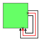
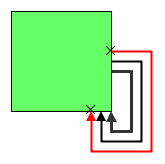
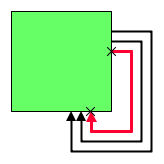
If you have multiple self-links at a node, they are bundled like multilinks. The bends of the self-links are shifted to avoid self-links overlapping each other. The multiself-links can be distributed in relation to the attachment position in various ways. The specified attachment position refers to the middle of the bundle, or it refers to the outermost link of the bundle, or it refers to the innermost link of the bundle. This is illustrated by the following figures. The attachment position is the same in all three cases and is indicated by the two small crosses (X), but the multiself-link distribution is variously centered, toward the inside of the bundle, or toward the outside of the bundle.
Multiself-link distribution | Figures showing the distribution |
Centered | |
Toward the inside of the multiself-link bundle | |
Toward the outside of the multiself-link bundle | |
Multiself-link distribution
In CSS
Add to the GraphLayout section:
multiSelfLinkDistribution: “INNER”;
In Java
Use the method:
setMultiSelfLinkDistribution(int distribution);
The valid values for distribution are given with the example of Uniform Length Edges layout:
IlvUniformLengthEdgesLayout.CENTERED IlvUniformLengthEdgesLayout.INNER IlvUniformLengthEdgesLayout.OUTER The offset between the bends of the self-links can be specified. These parameters have the same meaning as the corresponding parameters on general multilinks, but apply only to self-links that are multilink bundles.
In CSS
Add to the GraphLayout section:
multiSelfLinkOffset: "10";
multiSelfLinkMaxSpread: "60";
In Java
Use the methods:
setMultiSelfLinkOffset(float offset);
setMultiSelfLinkMaxSpread(float maxSpread);
The multiself-link offset is the offset between two neighboring self-links (or their bends). The value of maxSpread limits this offset to avoid having too much space used when you have too many multiple self-links. If the multiself-link offset is 10 and the value of maxSpread is 60, the effective offset is 10 if you have less than six multiself-links. If you have more multiself-links, the effective offset is reduced. For example, if you have 15 multiself-links, the effective offset will be 4 instead of 10 to ensure that the self-links are shifted at most 60 units apart from each other. If the self-link mode is one of the narrow modes, for example, NARROW_CONNECTED_RECTANGULAR, the effective offset is further limited by the size of the bounding box of the node where the self-links occur.
Copyright © 2018, Rogue Wave Software, Inc. All Rights Reserved.