Additional transformation techniques
Describes two more transformations that you can apply to symbols.

Explains how to change the position of an object in a symbol.
Explains how to make an object in a symbol rotate.
Transforming object position
The position of an object is set in function of the base object; the center of the base object is point 0,0. The base object is the central point of a symbol, it cannot change position. However, as shown in
Transforming an object, you can apply a transformation on a base object to change its width or height. Objects in higher layers can change position either by setting the x and y objects manually, or by binding a parameter to these values.
To change the position of an object:
1. In the Symbol Editor, create a new default symbol.
2. Select the Text object in the Symbol Outline pane.
3. Select the Transform tab in the Styling Customizer.
The x and y values in the Transform tab are set to 0, that is, Text is in the exact center of Shape (Base).
4. Type 5 in the x field and press ENTER.
You see Text moves to the right.
To change the position of an object using a parameter, use the method explained in
Transforming an object.
NOTE The object in the lowest layer of a grouped object is designated as the group’s base layer. As such, you can only customize its Width and Height objects, it cannot change position.
Rotating an object
Rotation is when an object turns clockwise or anti-clockwise on an axis you define. Like changes to the size or position of an object, the degree of rotation is set in the following ways:
Manually using the Transform tab in the Styling Customizer.
Automatically by binding the object to a parameter.
Using rotation, you can create an alternative graphic representation for real time change.
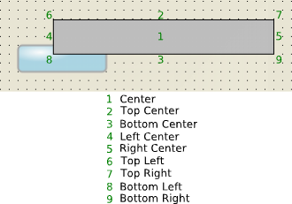
The axis on which an object rotates is chosen by setting the Center field in the Styling Customizer. The following figure shows the different axis points that can be defined on an object.
Rotation axis points for a symbol object
NOTE The axis is set on an object´s bounding box, that is, the smallest rectangle containing all parts of an object.
Setting the Angle field in the Styling Customizer to a positive value rotates the object clockwise, a negative value rotates anti-clockwise.
To create a rotating object in an imported SVG image:
1. In the Symbol Editor, create a new symbol.
2. Import image bamdial.svg from the directory <installdir>/jviews-diagrammer/bin/symboleditor/data/examples.
3. Delete the Text and Shape Objects.
SVG is now the base object.
4. Create a float parameter called progress.
5. Ungroup SVG.
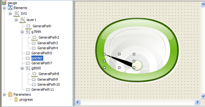
6. In the Symbol Outline pane, select the pointer object (General Path 6) and rename it pointer.
7. Select the Transform tab in the Styling Customizer.
8. Click the Bind button next to the Angle field.
9. Set the Parameter field to progress.
10. Enable Compute the transformation according to the following min/max values.
11. Set the following values:
Parameter Min: 0
Parameter Max: 100
Value Min: 0
Value Max 110.0. This is the maximum rotation for pointer.
12. Click OK.
13. Set the Center field to BottomRight.
14. Save this symbol as gauge in a gauges category in the bampalette.
15. Test your symbol.
You will see that the pointer rotates in function of changes in the value of progress.
The gauge symbol
Copyright © 2018, Rogue Wave Software, Inc. All Rights Reserved.