vtkPOLYSHADE Procedure
Renders a polygon object.
Usage
vtkPOLYSHADE, vertices, polygons
Input Parameters
Vertices—A (3, n) array containing the x-, y-, and z-coordinates of each vertex in data coordinates.
Polygons—An integer or longword array containing the indices of the vertices of each polygon. The vertices of each polygon should be listed either clockwise or counterclockwise order when observed from outside the surface. The vertex description of each polygon is a vector of the form [n, i0, i1, ... , in - 1], and the array polygons is the concatenation of the lists of each polygon.
Keywords
Name—Specify a name to be used to create this object. If an undefined variable is used or no name specified then a random name is used. This name can be used in calls to vtkCOMMAND to modify this object.
Color—An array expression, of the same dimensions as the number of vertices passes (the value “n” above), containing the color index at each vertex. Alternately an expression describing one color to be used for the entire polygonal surface or wireframe. If this keyword is omitted, a white surface is displayed.
To specify a single color, see the vtkWINDOW Procedure for possible ways to specify the color. If a two-dimensional array of colors is specified (for an image overlay) the shades variable can be in any of these formats:
Presentation—Name of a color to use for all annotation. See the file <RW_DIR>/vtk-3_2/lib/vtkcolornames.pro for a complete list of supported color names, where <RW_DIR> is the path to the PV-WAVE installation. If this keyword is present then the default annotation style for interactive viewing is replaced by one for presentation graphics, where all annotation is of uniform size and color, where the text always faces the camera, and where the origin of the z-axis is at the end of the y-axis.
Wireframe—When present and nonzero, a wire-frame mesh is drawn rather than a shaded surface.
LOD—If nonzero, a level-of-detail actor is created to aid in keeping a high frame-rate during frequent render requests due to user mouse interaction. If set to a value greater than 1, the number of points to use in the random cloud.
NoAxes—If set, no axes are created.
NoRotate—Does not perform any camera rotations. Used when a previous call to vtkSURFACE, vtkSCATTER or vtkPOLYSHADE has already set the camera angle.
NoErase—If nonzero, prevents the window from being erased to the background color before drawing the new scene. If not set, then all lights, cameras, and objects are removed from the scene before objects for the new scene are added.
Zoom—A scalar float, where values greater than 1 zoom-in on the image and values less than 1 zoom-out. Large values (such as 100) have the effect of enforcing a parallel projection. When the Presentation keyword is set, Zoom defaults to a large value so that the view fills the window and the projection is parallel.
Scale—A scalar or 3-element array specifying relative stretch factors for each dimension. This is useful when the aspect ratio of the unscaled scene is so large that some dimensions become difficult to view. Setting Scale to 1 makes all dimensions appear to be of equal length, while setting it to a 3-element array of values in the range [0,1] allows each dimension to be scaled individually.
Center—A 2-element array of values in the range [–1,1] which define the center of the view window. The default is [0,0].
These keywords are passed to vtkAXES:
Other keywords are listed below. For a description of each keyword, see Chapter 21: Graphics and Plotting Keywords.
Discussion
This procedure is similar to the POLYSHADE procedure for PV‑WAVE windows. Wireframes can be produced as well as surfaces shaded in one color or overlaid with an image. Transparency is also supported.
Example 1
pyramid_list = [[0,0,0],[0,1,0],[1,0,0],[1,1,0],[.5,.5,1]]
vertex_list=[3,0,2,4,3,2,3,4,3,3,1,4,3,1,0,4,4,0,1,3,2]
vtkPolyshade, pyramid_list, vertex_list, color='blue'
Example 2
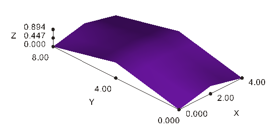
This example demonstrates the use of the Presentation keyword.
POLY_SURF, DIST(5,9)/5, v, p
vtkWINDOW, XSize=800, YSize=800, Background='white'
vtkPOLYSHADE, v, p, Presentation='black', $
XTicks=2, YTicks=2, ZTicks=2, $
XTitle='X', YTitle='Y', ZTitle='Z', $
Color='purple'
 |
Example 3
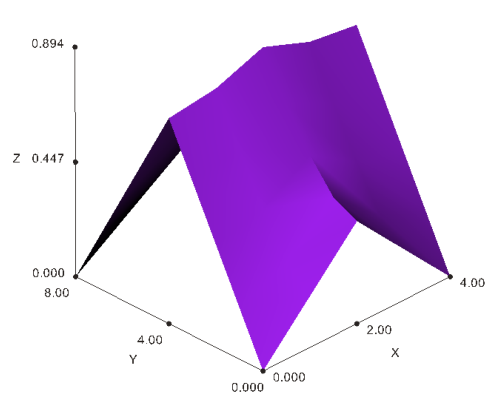
Building on Example 2, this example demonstrates how to scale the image from Example 2.
vtkPOLYSHADE, v, p, Presentation='black', $
Xticks=2, Yticks=2, Zticks=2, $
Xtitle='X', Ytitle='Y', Ztitle='Z', $
Color='purple', /Scale
 |
Example 4
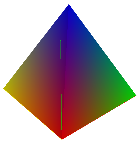
This example demonstrates the use of the Color keyword.
pyramid_list = [[0,0,0],[0,1,0],[1,0,0],[1,1,0],[.5,.5,1]]
vertex_list = [3,0,2,4,3,2,3,4,3,3,1,4,3,1,0,4,4,0,1,3,2]
color = FLOAT( [[1,0,0],[1,1,0],[0,1,0],[0,1,1],[0,0,1]] )
vtkWINDOW, XSize=800, YSize=800, Background='white'
vtkPOLYSHADE, pyramid_list, vertex_list, Color=color
 |
Example 5
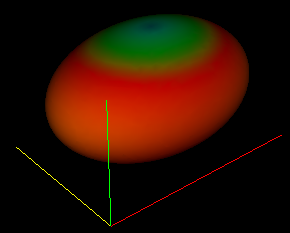
This example shows how SHADE_VOLUME is used to generate an isosurface of one parameter and color it by the values of a second parameter on that surface, in this case, an ellipsoidal isosurface colored according to its projection in the x-y plane.
x = LINSPACE( 41, -20.0, 1 )
a = x * x
r = TENSOR_ADD(2*a,3*a)
s = SQRT( TENSOR_ADD(a,r) )
r = REBIN( BYTSCL(SQRT(r),Top=191)+64b, 41, 41, 41 )
SHADE_VOLUME, s, 19, v, p, Shades=r
LOADCT, 4
vtkPOLYSHADE, v, p, Color=r
 |
While isosurfaces can be computed and displayed as above, an easier and more powerful method is provided by the ISOSURF procedure. Among other things it makes it easy to attach an arbitrary coordinate grid to the 3D array being isosurfaced.
See Also


