Architecture of the network component
A graphic component encapsulates a model, a view, and a controller. The network component, like all the other graphic components, is based on the MVC architecture, which means that it has a model, a view and a controller associated with it. For a general introduction to the MVC architecture, see
Architecture of graphic components. That section describes the classes and features of the network component that are specific to each module of the MVC architecture, and also explains the role of the adapter.

Gives an overview of the MVC architecture of the network component.
Describes the classes of the network model.
Describes the classes of the network view.
Describes the classes of the network controller.
Describes the classes of the network adapter.
Class overview
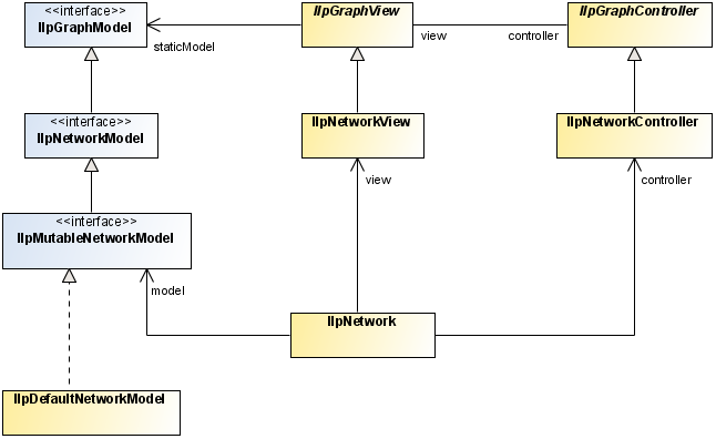
The MVC architecture of the network component is implemented by the following classes:
The class
IlpNetwork contains a model, a view, and a controller.
Representation objects to be displayed in the component must be added to the model. The network model recognizes the following objects:
Nodes
Links, which connect nodes
It displays the objects in a rectangular area, with scrollbars and a toolbar to let users navigate. The view displays the objects contained in the model or made accessible through container expansion of objects in the model.
The controller configures the view interactor, reacts to actions triggered by the interactor, and forwards these actions to a handler.
The following figure shows the main classes used by the network component.
Main classes used by the network component
The model
The model contains the representation objects used to produce the graphic objects in the view. The model describes the end points of links, and as such it models the topology of the network. The model allows the view to access contained objects through the method
getChildren. The model provides support for load-on-demand; that is, for adding child objects asynchronously when expanding network objects through the class
IlpExpansionStrategy.
Classes of the network model
The interface
IlpNetworkModel is implemented by the class
IlpDefaultNetworkModel. This class is automatically created when you instantiate
IlpNetwork.
JViews TGO provides the following interfaces for creating nodes and links:
JViews TGO supplies default implementations of these interfaces.
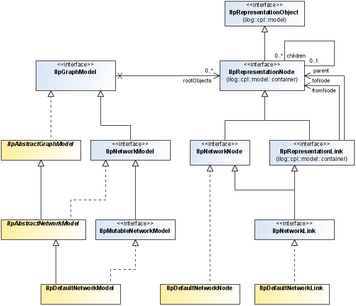
The following figure shows the classes used by the network model.
Classes used by the network model
Creating nodes and links in the network model
When you want to create a new node or link, use the default implementations:
To create a linkset, create several links with the same end nodes.
To set the end nodes of a link, apply the methods setFromNode (for the start node) and setToNode (for the end node).
A link cannot be displayed unless it has end nodes, but you can create the link before you create the end nodes.
The following examples show how to use the classes for creating nodes and links.
How to create a node
IlpDefaultNetworkNode node = new IlpDefaultNetworkNode(MyAttributes,null);
network.setPosition(node,new IlpPoint(100,200), IlpPositionSource.BACKEND);
model.addRootObject(node);
How to create a link
IlpDefaultNetworkLink link = new IlpDefaultNetworkLink(MyAttributes,null);
link.setFromNode(node1);
link.setToNode(node2);
model.addRootObject(link);
For convenience, the main methods of
IlpNetworkModel and
IlpMutableNetworkModel are also accessible from
IlpNetwork. Thus, the following statements are equivalent:
network.getModel().addRootObject(node);
and
network.addRootObject(node);
The view
The view displays a rectangular area of a theoretically infinite plane area. The view performs the following functions:
Displays a subset of the objects of the model
Allows navigation using scrollbars and provides a zoom facility
Assigns default positions to nodes that have no value for
position in the model
Assigns shapes to links that have none
Modifies link shapes when end nodes are moved
Provides a toolbar for choosing a view interactor
Optionally displays an overview window
Classes of the network view
The
IlpNetwork class automatically creates the concrete class
IlpNetworkView, which is provided for developing the network view. This class provides methods that allow you to configure the view in the following ways:
Set the overview panel to be displayed or not (here set to be displayed):
setOverviewVisibleFor convenience, these methods are also accessible from the class
IlpNetwork. They delegate to
IlpNetworkView.
For information on how to configure the network view in CSS, see
Configuring a network component through a CSS file.
For information on how to configure the network view through the API, see
How to configure the network view with the API.
Graphic objects in the network component
Graphic objects display as many details as possible within the limits of the display area and without loss of readability.
The network component uses only composite graphic objects. The graphic objects are created by the view renderer, which calls the appropriate object renderers to obtain the composite graphic objects. The view determines which object renderer is required to draw the graphic object that translates a particular representation object or attribute from the style sheet properties.
The following basic variations of graphic object exist in the network component:
Nodes—Nodes are the basic graphic objects and they are represented as network elements according to the conventions of the governing standards, such as ITU-T or ANSI, and the appropriate protocols.
Links—Links are the connections between nodes.
End-user interaction with a graphic object is handled by an object interactor. Object interactors handle the gestures of an end user when performing a task. Gestures consist of one or more mouse events to perform one task.
For more information on object interactors, see
Object interactors.
Graphic object classes
The graphic representation of each object displayed in the network component is implemented through the
IlpGraphic interface.
JViews TGO provides predefined network graphic objects that are produced by the default network component renderer. You can customize the rendering of the objects through CSS.
For custom business objects,
JViews TGO provides a default representation with a set of properties that can be customized to better represent your objects. If you prefer, you can also specify a new graphic representation by defining an
IlvGraphic class in the CSS. For more information, refer to
Customizing user-defined business objects. You can also refer to
<installDir> /samples/network/compositeGraphic to see how to create a new object representation by using the Rogue Wave® JViews composite graphics feature.
Predefined business objects already have a specific graphic representation that can only be changed through CSS customization by setting the object properties.
You can customize the graphic representation by adding new decorations. To see how to add new decorations to the objects using CSS, look at the decoration sample at
<installDir> /samples/network/decoration.
Network graphic object renderers
Object renderers in the network component create one graphic object that translates a complete representation object. No graphic objects are created that correspond to attributes of a representation object. Instead, subcomponents of graphic objects are created from attributes for example, a label can be created from the name attribute.
Such subcomponents are combined into composite graphic objects, like the link with secondary states and a label shown in
Link with secondary states and a label by using attachments.
Link with secondary states and a label
A composite graphic object constructed in this way looks like one object. The different instances of IlpGraphic used to build the graphic object cannot be distinguished as separate objects in the network. JViews TGO manages only the composite object. You cannot move the label separately from the link.
The controller
The controller is used for configuring view parameters, including layout and the background map. It manages the toolbar and the interactors: it determines which interactors are available from the toolbar.
The controller manages end-user interaction, such as object creation or move requests. It forwards these requests to the handler (see
The handler). It forwards all end-user requests to:
create objects
delete objects
and actions triggered by the end user to:
move objects
reshape objects
Classes of the network controller
The
IlpNetwork class automatically instantiates the class
IlpNetworkController.
Using the network controller
The normal way of customizing the behavior of the controller is to attach a handler through the API.
The default handler is the
IlpNetworkHandlerWithoutDataSource. When a mutable data source is connected to the network component, a new handler,
IlpNetworkHandlerWithDataSource, is attached to the controller. You can customize either of these handlers by extending them. To set a new handler, use the method
setHandler:
IlpNetwork network = ...
IlpNetworkController controller = network.getController();
IlpNetworkHandler myHandler = new MyCustomHandler();
controller.setHandler(myHandler);
Another controller configuration is to set the default view interactor through the method
setDefaultViewInteractor. See also
Interacting with the network view.
You can also customize the controller by using CSS rules in the network configuration. The following code gives an example. For more details, see
Configuring a network component through a CSS file.
How to customize the network controller through CSS
Interactor {
name: "Select";
}
This rule selects the default interactor.
The handler
In the same way as the adapter passes information about the objects in the data source to the network component, the handler passes information in the opposite direction, that is, from the network component to the data source.
The information notified in this way includes:
Actions triggered by interactors for
Creating objects in the data source
Removing objects from the data source
Changing attributes of objects in the data source
Changing the parent object of an object in the data source
Expanding and collapsing container objects
Propagating position changes of objects
The position changes are usually due to layout, zoom change, or interactors.
The handler has been designed to simplify the customization of user interactions without rewriting the controller.
Any user interaction with the network is processed by the network controller which delegates action to the network handler. The handler has two default implementations:
IlpNetworkHandlerWithDataSource is automatically attached to the controller when a data source is connected with the network component. User interactions are executed inside the data source that will notify the adapter, and the adapter in turn will notify the network model. In this particular use case, changes will be reflected on all network components, if any, connected to the data source.
There are four types of handler:
IlpNodeHandler to handle object additions, removals and updates, as well as relationship changes.
The
IlpNetworkHandler interface indirectly extends all four types of handler.
Custom subclasses of IlpNetworkHandler can be set using the controller.setHandler() method. It is possible to customize handlers separately by implementing the specific interface (for example, IlpNodeHandler) and setting it with the corresponding controller method (for example, controller.setNodeHandler()).
The handler has a reference to the data source in the form of an
IlpMutableDataSource, and to the network adapter.
The JViews TGO default handler is only compatible with data sources that implement the IlpMutableDataSource interface.
You can customize the behavior of the handler by subclassing the class
IlpNetworkHandlerWithDataSource. A particular method can be overridden for each of the possible actions.
A custom handler that is a subclass of IlpNetworkHandlerWithDataSource is automatically connected to a mutable data source.
It is the user's responsibility to manually connect a handler to a data source when one the following conditions applies:
The handler is not a subclass of
IlpNetworkHandlerWithDataSource.
The data source does not implement the interface
IlpMutableDataSource.
In this case, it is mandatory to create a custom handler and to design a way to connect the handler with the data source.
You can customize the way position changes are propagated by overriding the method
propagatePositionToDataSource. In a typical situation where the client is active, position changes are propagated to the data source. Therefore, this method returns
true by default. In a situation where the client has read-only access, you may want to allow only user-requested position changes or no position changes at all to be forwarded to the data source. You can achieve this result by allowing the method
propagatePositionToDataSource to return
false in the appropriate cases.
The handler is most often subclassed to allow you to customize the creation of new objects in the data source. The object interactors may need to be customized in the same way. A customized object creation interactor typically calls the controller method
createObject with specific properties. The controller then forwards these properties to the handler. Finally, the method
handleCreateObject of the handler parses the additional properties and creates the new objects.
By default, the handler creates new objects in two steps:
1. The ID of the new object is created with the method
createObjectId.
You can customize each step separately by overriding these methods in a subclass.
The adapter
The network adapter converts business objects into representation objects of type network node and network link. It is defined by the class
IlpNetworkAdapter.
Network adapters retrieve structural information (that is, parent/child relationship) about business objects from the associated data source and determine whether an object should appear as a root representation object by examining a list of origins. See
Setting a list of origins for details.
Like the tree adapter, the network adapter supports load on demand.
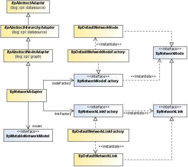
The following figure shows network adapter classes:
Network adapter classes
The network adapter creates either a node or a link representation object depending on the value returned by the method
getLinkInterface. If the return value is not null, then a link is created; otherwise, a node is created.
Nodes are created with an
IlpNetworkNodeFactory. By default, this factory is an instance of the class
IlpDefaultNetworkNodeFactory, which creates
IlpDefaultNetworkNode instances.
Similarly, links are created with an
IlpNetworkLinkFactory. By default, this factory is an instance of the class
IlpDefaultNetworkLinkFactory, which creates
IlpDefaultNetworkLink instances.
The network adapter handles the position or shape of objects. By default, it interprets every object attribute with the name
position as denoting the position of the object. You can use the method
setPositionAttribute in
IlpAbstractNodeAdapter to specify any other attribute to be used instead for all instances of a given
IlpClass.
You can create a network adapter implicitly by instantiating the
IlpNetwork component as shown in the following example.
How to create a network adapter by instantiating a network component
IlpNetwork ilpNetwork = new IlpNetwork();
IlpDataSource dataSource = new IlpDefaultDataSource();
ilpNetwork.setDataSource(dataSource);
If you want to configure the adapter, to set its origin for example, you must first retrieve it from the network component and then set it to the data source.
How to configure a network adapter
IlpNetwork ilpNetwork = new IlpNetwork();
IlpDataSource dataSource = new IlpDefaultDataSource();
// configure the adapter, for example set an origin
IlpNetworkAdapter adapter = ilpNetwork.getAdapter();
adapter.setOrigins(Collections.singletonList("origin"),false);
adapter.setDataSource(dataSource);
For information on how to configure the adapter in CSS, see
The Adapter rule.
Controlling the display of objects as containers
Unlike the tree adapter, the network adapter considers by default that objects are not containers. There are two conditions for an object to be a container: its
getContainerInterface method should not return
null and the property
expansion applying to that object should be set to
ExpansionType.IN_PLACE. By default, this property is set to
ExpansionType.NO_EXPANSION. For information on how to set a property value, see
Introducing cascading style sheets.
NOTE There is no way to represent an object in a network component as a container, if its
getContainerInterface returns
null.
Creating a temporary representation object
The network adapter supports temporary representation objects. These objects are placeholders that can be used in place of permanent representation objects for editing purposes and, more specifically, when new objects are created in the network view. When a business object corresponding to the temporary representation object is added to the data source, this temporary representation object is removed and replaced by the permanent representation of the business object. A filter, defined by
IlpFilter, is used to determine when the representation object of a business object added to the data source is a candidate to replace the temporary representation object. Filtering criteria can be of any kind.
The following example shows how to add a temporary representation object to a network adapter.
How to add a temporary representation object to a network adapter
First you create the temporary representation object, like this:
IlpDefaultNetworkNode temp=
new IlpDefaultNetworkNode(new IlpDefaultAttributeGroup());
Then you add it to the adapter along with the filtering criteria using the method
storeTemporaryRepresentationObject:
adapter.storeTemporaryRepresentationObject(temp, null, new IlpFilter() {
public boolean accept(Object o) {
IlpObject ilpO = (IlpObject)o;
return ilpO.getIdentifier().equals("right one");
}
};
The temporary representation object will be replaced by a permanent representation object as soon as a business object satisfying the filtering criteria is added to the data source.
Copyright © 2018, Rogue Wave Software, Inc. All Rights Reserved.