Network component services
Describes the services that are available for a network: view services, adapter services, and handler services.

Lists the different services available for a network.
Describes the predefined view interactors available to manage the behavior of the network view.
Describes how to use object interactors to associate behavior with business objects.
Describes the positioning facility for defining where a given object is displayed on the screen.
Gives an overview of the graph layout algorithms available for the network component.
Describes the automatic placement of labels in a network to facilitate legibility.
Describes how to customize the layer used for a given object.
Details the zooming modes available: physical zoom, logical zoom, and mixed zoom.
Describes how to use the background API to integrate various types of background in the network and equipment components.
Describes how to filter nodes displayed by the network component.
Details how to specify the business classes to be accepted for or excluded from display in the network component.
Describes how to set a list of origins to explicitly select the root nodes to be displayed by the network component.
Describes the node factory.
Describes the link factory.
Describes the expansion strategy used by the network adaptor to determine whether objects should be loaded in the network model.
Introduction to network component services
The services that are available for a network are of three kinds:
View services, related to the network view
Adapter services, related to the network model
Handler services, related to the network controller
Interacting with the network view
The
IlpNetwork allows you to associate behavior with the network view as a whole and with the business objects it contains.
JViews TGO provides predefined view interactors to manage the behavior of the network view. See
View interactors.
With the default view interactors, you can:
associate actions with mouse events and focus events
associate actions with keyboard events
define a pop-up menu factory to build a pop-up menu that displays in the view
Each view interactor works with one network view only and is managed by the network controller. A network view can have several interactors, but only one interactor is active at a time.
View interactors have two modes of operation:
Transient
Permanent
In transient mode, the view interactor removes itself from the network view when it has performed its action.
In permanent mode, the view interactor remains in the view until the controller removes it.
By default, view interactors are permanent.
View interactors can display a pop-up menu.
A view interactor has a context implemented through
IlpViewInteractionContext. When a user gesture is completed, the network view clones this context and makes it accessible through
IlpViewActionEvent.
The predefined view interactors are in the
ilog.tgo.interactor package and are subclasses of
IlvManagerViewInteractor. When one of these interactors is installed, it must be wrapped in an
IlpViewsViewInteractor.
How to wrap a predefined view interactor when installing it
IlvManagerViewInteractor iltInteractor = new Ilt...Interactor();
IlpViewInteractor ilpInteractor =
new IlpViewsViewInteractor(iltInteractor);
controller.setViewInteractor(ilpInteractor);
Setting the view interactor
The method
setViewInteractor allows you to set the view interactor, that is, the object-independent interactor, which is active at a given moment in the view. This interactor is replaced whenever the end user activates a different interactor. Such activation occurs, for example, when the user clicks a toolbar button.
Some interactors are one-shot interactors, that is, they have the attribute permanent:false in CSS. When such an interactor finishes its interaction, it is replaced by the default view interactor.
To customize through CSS, refer to
The Interactor rule.
View interactor and default view interactor
When you use the
setViewInteractor method you are attaching the specified interactor directly to the view. On the other hand, the
setDefaultViewInteractorallows you to define the interactor that will be attached when the current interactor is detached from the view and no other interactor is attached. The default interactor is not attached automatically to the view, so it will not be available immediately.
The following example combines both methods:
// Configuring the default view interactor and making
// it active
IltSelectInteractor selInteractor = new IltSelectInteractor();
selInteractor.setEditingAllowed(true);
IlpViewsViewInteractor viewsInteractor =
new IlpViewsViewInteractor(selInteractor);
network.setDefaultViewInteractor(viewsInteractor);
network.setViewInteractor(viewsInteractor);
In this example, you define the default view interactor through the call to setDefaultViewInteractor, and you activate it through the call to setViewInteractor so that it is immediately available.
How to associate an action with a mouse event and modifier in the network view
You can associate actions with mouse events, with or without modifiers, by using either CSS or the API.
The following extract shows how to customize the default view interactor in CSS:
Network {
interactor: true;
}
Interactor {
viewInteractor: @+viewInt;
}
Subobject#viewInt {
class: 'ilog.cpl.graphic.views.IlpViewsViewInteractor';
action[0]: @+viewAction0;
}
Subobject#viewAction0 {
class: 'ilog.cpl.interactor.IlpGestureAction';
gesture: BUTTON3_CLICKED;
modifiers: shift;
action: @+myAction;
}
Subobject#myAction {
class: 'my.custom.ActionImplementation';
}
The same configuration can be achieved through the API, as follows:
IlpNetwork network = // ...
// Retrieve the view interactor
IlpViewInteractor viewInteractor = network.getDefaultViewInteractor();
// Create an actionAction
myAction = new MyAction();
// Clicking the 3rd mouse button will trigger myAction
viewInteractor.setGestureAction(IlpGesture.BUTTON3_CLICKED,
InputEvent.SHIFT_DOWN_MASK,myAction);
You can also customize the actions that are associated with the interactors defined in the network component toolbar. This configuration is done with the toolbar button definition.
How to associate an action with a mouse event for a network ToolBar button interactor
You can associate actions with mouse events when one of the interactors defined in the network component toolbar is active. The following CSS extract illustrates this configuration:
Network {
toolbar: true;
}
ToolBar {
enabled: true;
button[0]: @+SelectButton;
}
Subobject#SelectButton {
actionType: "Select";
usingObjectInteractor: true;
opaqueMove: true;
action[0]: @+action0;
}
Subobject#action0 {
gesture: BUTTON1_DOUBLE_CLICKED;
class: 'my.custom.ActionImplementation';
}
In this configuration, the action ActionImplementation is triggered when a double-click event occurs while the selection interactor is set in the network view. You can define any list of actions associated with gestures by using the indexed property action. To be accepted by the CSS customization, the action class must be a JavaBean™.
The CSS to associate an action with a mouse event and a modifier is slightly different:
Subobject#SelectButton {
actionType: "Select";
usingObjectInteractor: true;
opaqueMove: true;
action[0]: @+gestureAction0;
}
Subobject#gestureAction0 {
class: 'ilog.cpl.interactor.IlpGestureAction';
gesture: BUTTON1_DOUBLE_CLICKED;
modifiers: 'shift,control';
action: @+action0;
}
Subobject#action0 {
class: 'my.custom.ActionImplementation';
}
You can find out whether this event occurred on an IlpObject by means of the following code (which should be in your Action implementation):
How to check whether a given action occurred in the network view interactor
// Implementation of the ActionListener interface
public void actionPerformed(ActionEvent e) {
// JTGO interactors use IlpViewActionEvent
IlpViewActionEvent viewEvent = (IlpViewActionEvent)e;
// Get the IlpObject (if any) where the interaction occurred
IlpObject ilpObj = viewEvent.getIlpObject();
// Perform operation on the given object
}
How to associate an action with a keyboard event in the network view
You can associate actions with keyboard events by using either CSS or the API.
The following extract shows how to proceed in CSS:
Network {
interactor: true;
}
Interactor {
viewInteractor: @+viewInt;
}
Subobject#viewInt {
class: 'ilog.cpl.graphic.views.IlpViewsViewInteractor';
action[0]: @+viewAction0;
}
Subobject#viewAction0 {
class: 'ilog.cpl.interactor.IlpKeyStrokeAction';
keyStroke: 'typed D';
action: @+myAction;
}
Subobject#myAction {
class: 'my.custom.ActionImplementation';
}
The same configuration can be achieved through the API, as follows:
// Create an actionAction myAction = new MyAction();
// Typing CTRL+D will trigger myAction
viewInteractor.setKeyStrokeAction(KeyStroke.getKeyStroke('D',java.awt.Event.CTRL_MASK),
myAction);
You can also customize the keystroke actions that are associated with the interactors defined in the network component toolbar. This configuration is performed with the toolbar button definition. The following CSS extract illustrates how this can be achieved:
How to associate an action with a keyboard event for a network toolbar button interactor
You can associate actions with keyboard events when one of the interactors defined in the network component toolbar is active. The following CSS extract illustrates this configuration:
Network {
toolbar: true;
}
ToolBar {
enabled: true;
button[0]: @+SelectButton;
}
Subobject#SelectButton {
actionType: "Select";
usingObjectInteractor: true;
opaqueMove: true;
action[0]: @+action0;
}
Subobject#action0 {
key: "control A";
class: "ilog.cpl.graph.action.IlpSelectAllObjectsAction";
}
In this configuration, the action " IlpSelectAllObjectsAction " is triggered when a Control-A keyboard event occurs while the selection interactor is set in the network view. You can define any list of actions associated with keyboard events by using the indexed property action. To be accepted by the CSS customization, the action class must be a JavaBean.
How to define a pop-up menu factory for the network view
You can customize a pop-up menu factory for the network view either through CSS or through the API.
The following extract shows how to add a pop-up menu factory through CSS:
Network {
interactor: true;
}
Interactor {
viewInteractor: @+viewInt;
}
Subobject#viewInt {
class: 'ilog.cpl.graphic.views.IlpViewsViewInteractor';
popupMenuFactory: @+viewPopupMenuFactory;
}
Subobject#viewPopupMenuFactory {
class: MyPopupMenuFactory;
}
The same configuration can be achieved through the API, as follows:
// Subclass IlpAbstractPopupMenuFactory, which has useful shortcuts
IlpPopupMenuFactory popupMenuFactory = new IlpAbstractPopupMenuFactory() {
// Add the identifier of each of the selected objects to the menu
public JPopupMenu createPopupMenu (IlpObjectSelectionModel ilpSelectionModel)
{
// Create an empty popup menu
JPopupMenu menu = new JPopupMenu();
// Access the selected objects from the selection model
Collection selectedObjects = ilpSelectionModel.getSelectedObjects();
// fill the menu according to the current selection
return menu;
}
};
The following code shows you how to associate the defined pop-up menu factory with the network component:
How to associate a pop-up menu factory with the network component
// Set the popup menu factory to the view interactor
viewInteractor.setPopupMenuFactory(popupMenuFactory);
You can also customize a pop-up menu factory that is associated with the interactors defined in the network component toolbar. This configuration is performed with the toolbar button definition. The following CSS extract illustrates how this can be achieved:
How to define a pop-up menu factory for a network toolbar button interactor
The following CSS extract illustrates this configuration:
Network {
toolbar: true;
}
ToolBar {
enabled: true;
button[0]: @+SelectButton;
}
Subobject#SelectButton {
actionType: "Select";
usingObjectInteractor: true;
opaqueMove: true;
popupMenuFactory: @=viewPopupMenuFactory;
}
Subobject#viewPopupMenuFactory {
class: 'AlarmPopupMenuFactory';
}
The pop-up menu factory is customized using property popupMenuFactory in the button configuration. To be accepted during the CSS customization, the pop-up menu factory class must be a JavaBean.
Selection interactor
The
IltSelectInteractor class allows you to select, move, and interact directly with objects. You can:
Click an object to select it and deselect all other objects.
Use Shift-click to select an unselected object or to deselect a selected object while keeping other prior selected objects selected.
Drag a selection rectangle to select all objects within this rectangle.
Drag one selected object and thereby cause all other selected objects to move in relation to it.
If setUsingObjectInteractor(true) is called on the interactor, then you can also:
Use other gestures that are understood by a specific object interactor.
You can configure the selection interactor to use Ctrl-click instead of Shift-click for multiple selection.
How to configure the selection interactor for multiple selection in the network view
In CSS, use the following rules:
Subobject#SelectButton {
multipleSelectionModifier: "java.awt.event.InputEvent.CTRL_MASK";
selectionModifier: "java.awt.event.InputEvent.SHIFT_MASK";
}
In the API, use the following code:
setMultipleSelectionModifier(InputEvent.CTRL_MASK);
setSelectionModifer(InputEvent.SHIFT_MASK);
Group reshape interactor
The
IltEditGroupInteractor class allows you to change the shape of rectangular, polygonal, and linear groups (
IltGroup,
IltLinearGroup,
IltRectGroup and
IltPolyGroup). Clicking an object starts shape editing interaction. Clicking the background ends it.
For polygonal and linear groups:
Dragging a vertex moves it.
Ctrl-click on a vertex removes it.
Ctrl-click on an edge adds a vertex at that point on the edge.
Make rectangular node interactor
The
IltMakeRectGroupInteractor class creates a node with a rectangular shape (
IltRectGroup). One corner of the rectangle is denoted by the point where the cursor is located when the mouse button is released. Make sure that you do really move the mouse between the time when you press and the time when you release the mouse button. Otherwise, the shape is created empty and the node might be invisible.
Make polygonal node interactor
The
IltMakePolyGroupInteractor class creates a node with a polygonal shape (
IltPolyGroup). A point is added each time the user clicks. Double-clicking marks the last point to be added.
Make polyline node interactor
The
IltMakeLinearGroupInteractor class creates a node with a polyline shape (
IltLinearGroup). A point is added each time the user clicks. Double-clicking marks the last point to be added.
Make link interactor
The
IltMakeLinkInteractor class creates links (
IltLink) between nodes. This interactor works in the following way: the user clicks one node and then goes on dragging the mouse over another node so that the two nodes are selected. When the user releases the mouse, a link is drawn between the two nodes.
For a detailed description of interactors and gestures, refer to
Interacting with the graphic components.
Interacting with the network objects
The topic
Interacting with the network view describes how to set an interactor on the entire network view. You can also associate behavior with business objects (a whole class or individual objects), as well as with individual object instances.
To do so, you use object interactors, which offer you the same possibilities as the view interactor:
Associating actions with mouse events
Associating actions with keyboard events
Defining a pop-up menu factory to build a pop-up menu that displays on representation objects
An object interactor handles any event occurring to the object with which it is associated, provided the view interactor has enabled the use of object interactors. You can check this with the isUsingObjectInteractor method or modify it with the setUsingObjectInteractor method.
Object interactors are enabled by default.
No default interactor is associated with any object. To associate actions with mouse or keyboard events, or to define a pop-up menu factory, you first have to create an instance of
IlpObjectInteractor. You can use the
IlpDefaultObjectInteractor class, extend it, or create your own implementation.
How to associate an object interactor with a network component object
You can associate an object interactor with a representation object by using either CSS or the API.
The following extract shows how to proceed in CSS:
Network {
interactor: true;
}
object."ilog.tgo.model.IltNetworkElement" {
interactor: @+objInteractor;
}
Subobject#objInteractor {
class: 'ilog.cpl.interactor.IlpDefaultObjectInteractor';
}
The same configuration can be achieved through the API, as follows:
IlpNetwork network = // ...
IlpNetworkController networkController = network.getController();
// Create an object interactor
IlpObjectInteractor objectInteractor = new IlpDefaultObjectInteractor();
networkController.setObjectInteractor( bo, objectInteractor);
// Configuring the specific object interactor is similar to configuring
// a view interactor.
objectInteractor.setGestureAction(IlpGesture.BUTTON3_CLICKED, new MyAction());
Actions related to mouse and keyboard events can be customized in the same way as for the view interactor. You can also define a pop-up menu factory in the same way as for the view interactor. Refer to
Interacting with the network view.
An object interactor can also be associated with a specific decoration that is part of the business object graphic representation in the network view. Each decoration represents a business attribute in the model. Therefore the customization of the interactor for a specific decoration takes into account the business object and a business attribute as illustrated below:
How to associate an object interactor with the label decoration in a network component object
You can associate an object interactor with one of the graphic decorations of the object by setting the interactor to the business attribute that is represented. You can do it using CSS or the API.
The following extract shows how to proceed in CSS:
Network {
interactor: true;
}
object."ilog.tgo.model.IltNetworkElement/name" {
interactor: @+objInteractor;
}
Subobject#objInteractor {
class: 'ilog.cpl.interactor.IlpDefaultObjectInteractor';
}
The same configuration can be achieved through the API, as follows:
IlpNetwork network = // ...
IlpNetworkController networkController = network.getController();
// Create an object interactor
IlpObjectInteractor objectInteractor = new IlpDefaultObjectInteractor();
networkController.setObjectInteractor( bo, IltObject.NameAttribute,
objectInteractor);
// Configuring the specific object interactor is similar to configuring
// a view interactor.
objectInteractor.setGestureAction(IlpGesture.BUTTON3_CLICKED, new
MyAction());
Actions related to mouse and keyboard events can be customized in the same way as for the view interactor. You can also define a pop-up menu factory in the same way as for the view interactor. Refer to
Interacting with the network view.
For a detailed description of interactors and gestures, refer to
Interacting with the graphic components.
Positioning
This facility is for defining where a given object is displayed on the screen.
Each representation object has the option of carrying a position. The position data can originate from the back end (mapped automatically from an attribute of the corresponding business object, or manually from a separate source), from computation by a default layout algorithm in the network view, or from explicit end-user gestures to move or reshape nodes in the view. It is possible to retrieve the origin of the position data through the
IlpPositionSource enumeration. There are three possible origins for the position of representation objects:
BACKEND : The position has been set by the adapter when creating the representation object.
LAYOUT : The position has been set in the view by an automatic layout algorithm (either the node layout or the link layout).
USER : The position has been set by the user through interactors.
To retrieve the position origin, you need to access the method getPositionSource in the network view.
The position implements the
IlpPosition interface.The following supplied types implement
IlpPosition :
The position can be attached to a representation object through the method
setPosition and retrieved through the method
getPosition of the network view (
IlpNetworkView).
A position converter is used to convert positions in the network model to positions in the network view or vice versa. The position converter implements the
IlpPositionConverter interface.
JViews TGO provides a default position converter (
IlpDefaultPositionConverter) for the predefined business objects position data. The following predefined position types are supported:
Since the network view already supports these position types, the
IlpDefaultPositionConverter does nothing else than verify that the given position is one of the predefined types.
Positioning using geographic coordinates
A more complex converter is provided for geographic coordinates (
IlpGeographicPositionConverter). It extends the default position converter to support the following types of positions:
When you use a background map, you can give the positions of objects directly in geographic coordinates (latitude/longitude). The conversion to screen coordinates is performed by using an instance of
IlpGeographicPositionConverter. You can parameterize this converter through classes that are part of the Rogue Wave® JViews Maps product: an
IlvProjection or an
IlvMathTransform, optionally followed by an
IlvTransformer. Refer to
The two coordinate systems.
How to parameterize the geographic position converter
// Set the position converter. It converts the geographic coordinates
// of the objects in the XML file to planar (x,y) coordinates.
IlvProjection projection =
new IlvEquidistantCylindricalProjection();
IlvTransformer t = new IlvTransformer(0.00001,0,0,0.00001,1,6.5);
IlpPositionConverter converter =
new IlpGeographicPositionConverter(projection,true,t);
networkComponent.setPositionConverter(converter);
You can also parameterize the geographic position converter through CSS by using the following steps:
1. Define a converter class with an empty constructor.
public class MyConverter extends IlpGeographicPositionConverter {
public MyConverter() {
super(new IlvEquidistantCylindricalProjection(),
true,
new IlvTransformer(0.00001, 0, 0, 0.00001, 1, 6.5));
}
}
2. Reference the converter class in a CSS file as follows.
Positioning {
positionClass: 'ilog.cpl.network.IlpGeographicPosition';
converterClass: 'my.package.MyConverter';
}
Important The parameters used to configure an
IlpGeographicPositionConverter should conform to the georeferencing configuration of the background map in use. For details, see
Background support.
You can define your own application-specific implementation of the
IlpPosition interface, for example, you could implement polar coordinates. When you define your own implementation of
IlpPosition, you must also attach the corresponding implementation of the
IlpPositionConverter to the view. In this particular case, you would attach a converter from polar positions to the predefined view position types.
When an object has no attached position, the view assigns a position to the corresponding graphic object. The position is assigned through the layout mechanism (node layout for positioning nodes, and link layout for shaping links).
If the position of an object changes due to user interaction, the controller requests the handler to confirm the change.
Layout
JViews TGO makes use of the Rogue Wave® JViews graph layout algorithms. Each IlpNetworkView can be connected to several node algorithms and one link algorithm.
The
node layout algorithms are:
The
link layout algorithms can be:
NOTE The difference between Ilv and Ilt link layout algorithms is that Ilt algorithms support connection ports whereas Ilv algorithms do not.
The detailed description of all the graph layout algorithms can be found in the Rogue Wave JViewsDiagrammer Using Graph Layout Algorithms documentation.
In case of multiple layouts, one layout can be set to be applied automatically whenever the contents of the view changes, while the others can be applied on demand. If the view contains subnetworks, you can specify different node layouts and a different link layout for the subnetworks.
To configure the layouts, it is recommended to use CSS (see
Configuring a network component through a CSS file). Using CSS, you can also configure per-object layout parameters.
If a layout takes too much time to execute, or if you want to add toolbar buttons to execute a layout, you can configure the layout for the view and subnetworks, then execute it on demand by using the API method
performAttachedLayout. The advantage of this method over the method
performLayoutOnce is that the layout remains attached to the view, therefore storing any previously-defined configuration.
The class
IlpNetworkView provides the following methods to handle the layout operation:
void setNodeLayout (
IlvGraphLayout layout, boolean perform). This method sets the given layout as the default for this
IlpNetworkView. If the
perform parameter is set to
true, the layout is applied to the objects immediately. With this method the layout is executed every time the network content changes.
void
setLinkLayout (IlvGraphLayout layout, boolean perform). This method sets the given layout as the default link layout for this instance of
IlpNetworkView. If the
perform parameter is set to
true, the layout is applied to the links immediately. With this method the layout is executed every time the network content changes.
public void performLayoutOnce(IlvGraphLayout layout). This method executes the layout algorithm once on the manager content.
void startDelayingUpdates(). This method suspends temporarily the layout operations. This mechanism avoids unnecessary computation when you intend to perform a sequence of operations that affect the network layout.
void endDelayingUpdates(). This method resumes the layout operations suspended by a call to the method
startDelayingUpdates. Any operation that requests a layout recalculation is suspended when it is executed between
startDelayingUpdates and
endDelayingUpdates calls.
void setGraphLayouts(IlvGraphLayout[] layouts). This method sets the given graph layouts for this
IlpNetworkView. Several graph layouts can be set to position nodes in the view. One of them can be configured to be executed every time the network contents changes. This method does not apply the layout to the nodes immediately. All the graph layouts given as argument to the method are attached to the view.
void setGraphLayouts(int index, IlvGraphLayout layout). This method sets a new graph layout for the
IlpNetworkView or replaces an existing graph layout. This method does not apply the layout to the nodes immediately.
IlvGraphLayout[] getGraphLayouts(). This method returns the graph layouts that have been configured for the view.
IlvGraphLayout getGraphLayouts(int index). This method returns the graph layout that is configured for the view at the given index.
void setAutoLayoutIndex (int index). This method indicates, from the list of graph layouts that have been configured using method
setGraphLayouts, which one is executed automatically when the contents of the view changes.
int getAutoLayoutIndex(). This method returns the index of the graph layout that is executed automatically when the contents of the view changes.
void setGraphLayouts(IlpRepresentationObject ro, IlvGraphLayout[] layouts). This method allows you to set graph layouts that can be used to position nodes in the subnetwork corresponding to the given representation object. One of the graph layouts can be configured to be executed automatically when the contents of the subnetwork changes. The other graph layouts are attached to the view and can be performed on demand.
void setGraphLayouts(IlpRepresentationObject ro, int index, IlvGraphLayout layout). This method allows you to set or replace a graph layout used to position nodes in a subnetwork.
IlvGraphLayout[] getGraphLayouts(IlpRepresentationObject ro). This method returns the graph layouts that have been configured for the given subnetwork.
IlvGraphLayout getGraphLayouts(IlpRepresentationObject ro, int index). This method returns the graph layout that has been configured for the given subnetwork at the given index.
void setAutoLayoutIndex(IlpRepresentationObject). This method defines which graph layout configured using
setGraphLayouts(IlpRepresentationObject) will execute automatically when the contents of the subnetwork changes.
int getAutoLayoutIndex(IlpRepresentationObject). This method returns the graph layout that has been configured to execute automatically when the contents of the subnetwork changes.
void setLinkLayout(IlpRepresentationObject). This method defines a link layout for the given subnetwork.
void performAttachedLayout(int index). This method executes the layout that has been configured for the given index, recursively in the object tree. The layout has been already attached to the view and keeps the configuration whenever it is performed.
IlvGraphic getLayoutProxy(IlpRepresentationObject). This method returns the graphic object corresponding to the given representation object for layout purposes. This method should be used if you need to set per-object layout properties to configure the layout algorithms.
NOTE Graphical parameters, such as the layout region, that are passed to the graph layout are expressed in view coordinates. Therefore, if you have expressed these parameters in stationary coordinates, you must transform them to view coordinates (by applying network.getView().getCompositeGrapher().getZoomTransformer() network.getManagerView().getTransformer() ) before passing them to the graph layout.
How to use hierarchical node layout in the network component
In CSS, use the following rules:
Network {
graphLayout: true;
}
GraphLayout {
class: 'ilog.views.graphlayout.hierarchical.IlvHierarchicalLayout';
flowDirection: Bottom;
levelJustification: Top;
globalLinkStyle:
'ilog.views.graphlayout.hierarchical.IlvHierarchicalLayout.POLYLINE_STYLE';
connectorStyle:
'ilog.views.graphlayout.hierarchical.IlvHierarchicalLayout.EVENLY_SPACED_PINS';
}
Note that the full class path is required for the properties globalLinkStyle and connectorStyle for the type converter to locate and convert the constants.
For an example of a CSS link layout, refer to
The LinkLayout rule.
In the API, use the following code:
IlvHierarchicalLayout layout = new IlvHierarchicalLayout();
layout.setFlowDirection (IlvDirection.Bottom);
layout.setLevelJustification (IlvDirection.Top);
layout.setGlobalLinkStyle (IlvHierarchicalLayout.POLYLINE_STYLE);
layout.setConnectorStyle (IlvHierarchicalLayout.EVENLY_SPACED_PINS);
network.setNodeLayout(layout);
NOTE All layouts to be used with
JViews TGO must be set in view coordinate mode. This mode is automatically set when you install layouts through
setNodeLayout,
setLinkLayout setLinkLayout, or
performLayoutOnce. If you call the method
performLayout directly, you must first set the mode:
layout.setCoordinatesMode(IlvGraphLayout.VIEW_COORDINATES); Even when you decide to use a certain node or link layout, you may want some links or nodes to be pinned; that is, you may want to keep a certain element in a specified position that is not affected when the layout is executed on a network.
You can achieve this effect by using the following methods defined in IlvGraphLayout :
setPreserveFixedLinks (boolean preserve). This method determines whether or not the layout will preserve the position of the registered links.
setPreserveFixedNodes (boolean preserve). This method determines whether or not the layout will preserve the position of the registered nodes.
void setFixed (Object obj /* link or node */, boolean fix). This method determines whether or not the given object will be fixed in the network.
boolean isFixed (Object obj). The return value indicates whether or not the given object is marked to be fixed. The object to be passed is an
IlvGraphic belonging to the
IlpGraphic that represents the object and
not the
IlpGraphic or
IlpRepresentationObject itself.
void unfixAllLinks() void unfixAllNodes() How to set a link to fixed shape and a node to fixed position in the network view
The following code illustrates how you can set a given link to have a fixed shape and a given node to have a fixed position in the network.
In CSS, use the following rules:
Network {
graphLayout: true;
linkLayout: true;
}
LinkLayout {
class: 'ilog.views.graphlayout.link.IlvLinkLayout';
}
GraphLayout {
layouts[0]: @+treeLayout;
}
Subobject#treeLayout {
class: 'ilog.views.graphlayout.tree.IlvTreeLayout';
}
#Link:linkLayoutRenderer {
fixed: true;
}
#NE1:graphLayoutRenderer:tree {
fixed: true;
}
In the API, use the following code:
IlvGraphLayout layout = networkView.getLinkLayout();
layout.setPreserveFixedLinks (true);
IlpRepresentationObject linkRO = networkAdapter.getRepresentationObject(link);
layout.setFixed(networkView.getLayoutProxy(linkRO));
layout = networkView.getNodeLayout();
layout.setPreserveFixedNodes (true);
IlpRepresentationObject neRO = networkAdapter.getRepresentationObject(ne);
layout.setFixed(networkView.getLayoutProxy(neRO));
When the position or shape of an object is not handled by the layout, you must set it by calling the method
setPosition (or
IlpNetworkView.setPosition ).
JViews TGO provides a default layout which uses IlvShortLinkLayout to shape and position links. This default layout sets all objects without an attached position to (0,0).
How to use multiple node layouts in a network view
In this scenario, two node layouts are configured for the network view. The first one is configured to be executed automatically.
In CSS, use the following rules:
Network {
graphLayout: true;
}
GraphLayout {
layouts[0]: @+hierarchicalLayout;
layouts[1]: @+treeLayout;
autoLayoutIndex: 0;
}
Subobject#hierarchicalLayout {
class: 'ilog.views.graphlayout.hierarchical.IlvHierarchicalLayout';
flowDirection: Bottom;
levelJustification: Top;
globalLinkStyle: POLYLINE_STYLE;
connectorStyle: EVENLY_SPACED_PINS;
}
Subobject#treeLayout {
class: 'ilog.views.graphlayout.tree.IlvTreeLayout';
flowDirection: Bottom;
}
The same layout that is applied to the network view will be applied to the whole subnetwork hierarchy.
In the API, use the following code:
IlvHierarchicalLayout layout = new IlvHierarchicalLayout();
layout.setFlowDirection (IlvDirection.Bottom);
layout.setLevelJustification (IlvDirection.Top);
layout.setGlobalLinkStyle (IlvHierarchicalLayout.POLYLINE_STYLE);
layout.setConnectorStyle (IlvHierarchicalLayout.EVENLY_SPACED_PINS);
IlvTreeLayout treeLayout = new IlvTreeLayout();
layout.setFlowDirection(IlvDirection.Bottom);
network.setGraphLayouts(new IlvGraphLayout[] { layout, treeLayout });
network.getView().optimizeLayout();
To execute the tree layout in the view, use the method performAttachedLayout, where the index is the one defined in the CSS configuration, as illustrated below:
network.getView().performAttachedLayout(1);
How to use different layouts for the view and subnetworks
It is also possible to configure some subnetworks with layout algorithms that are different from the network view.
NOTE If the subnetworks have intergraph links, the link layout renderer must be enabled, otherwise the intergraph links will not be routed.
In this scenario, the object ' SubNetwork1 ' positions its nodes using a tree layout algorithm, while the nodes in the main view are positioned using a grid layout.
In CSS, use the following rules:
Network {
graphLayout: true;
linkLayout: true;
}
LinkLayout {
class: 'ilog.views.graphlayout.link.IlvLinkLayout';
}
GraphLayout {
layouts[0]: @+gridLayout;
}
Subobject#gridLayout {
class: 'ilog.views.graphlayout.grid.IlvGridLayout';
}
#SubNetwork1:graphLayoutRenderer {
layouts[0]: @+treeLayout;
}
Subobject#treeLayout {
class: 'ilog.views.graphlayout.tree.IlvTreeLayout';
}
In the API, use the following code:
IlvGridLayout gridLayout = new IlvGridLayout();
network.setGraphLayouts(new IlvGraphLayout[] { gridLayout });
IlvTreeLayout treeLayout = new IlvTreeLayout();
layout.setFlowDirection(IlvDirection.Bottom);
IlpRepresentationObject ro =
network.getAdapter().getRepresentationObject("SubNetwork1");
network.getView().setGraphLayouts(ro, new IlvGraphLayout[] { treeLayout });
network.getView().optimizeLayout();
How to configure per-object layout properties in the network component
Some layout algorithms require a specific configuration in order to be properly executed. For example, the bus layout needs to have a bus object specified; or the tree layout, for which you may want to specify the root node prior to the layout execution. Starting from JViews TGO 7.5, you can configure these properties using CSS, as illustrated below:
Network {
graphLayout: true;
}
GraphLayout {
layouts[0]: @+busLayout
}
Subobject#busLayout {
class: 'ilog.views.graphlayout.bus.IlvBusLayout';
horizontalOffset: 50;
verticalOffsetToLevel: 50;
verticalOffsetToPreviousLevel: 40;
margin: 30;
marginOnBus: 50;
}
// Configure the bus object as the bus in the layout
// All layout configuration uses the 'graphLayoutRenderer'
// and the graph layout name pseudoclasses
#BUS:graphLayoutRenderer:bus {
bus: true;
}
// Configure the bus to route the links that connect the
// bus to the nodes
#BUS {
linksConnectToBase: true;
}
or, using the API:
IlvBusLayout busLayout = new IlvBusLayout();
network.setGraphLayouts(new IlvGraphLayout[] { busLayout });
IlpRepresentationObject ro =
network.getAdapter().getRepresentationObject("BUS");
IlvGraphic layoutProxy = network.getView().getLayoutProxy(ro);
busLayout.setBus((IlvPolyPointsInterface)layoutProxy);
How to disable the per-object layout properties configuration in the network view
By default, per-object layout parameters can be configured using CSS. However, if you are not interested in this feature, you can disable it by setting the property usePerObjectParamenters in the graph layout renderer and link layout renderer. Disabling the per-object layout properties configuration speeds up significantly the rendering process.
Network {
graphLayout: true;
linkLayout: true;
}
LinkLayout {
class: 'ilog.views.graphlayout.link.IlvLinkLayout';
usePerObjectParameters: false;
}
GraphLayout {
layouts[0]: @+treeLayout;
usePerObjectParameters: false;
}
Label layout
JViews TGO allows you to place labels in a network automatically to make them easier to read. This placement overrides the default placement of labels in JViews TGO, namely:
Below network elements
At the center of gravity of groups
Label layout allows you to reduce overlap between labels and other objects in the current view. Therefore, it is particularly useful for positioning labels on links.
Network Links without Label Layout shows labels positioned by default.
Network Links with Label Layout shows the same links with customized positioning of the labels through label layout.
Network Links without Label Layout
Network Links with Label Layout
NOTE Label layout tries to find the best position for your labels, but sometimes even this mechanism does not achieve attractive results. To get the best results, leave large spaces between network objects.
Label layout in JViews TGO uses the label layout of Rogue Wave® JViews. See the Rogue Wave JViewsDiagrammer Using Graph Layout Algorithmsdocumentation for more details on label layout.
Using label layout
JViews TGO provides the
IltAnnealingLabelLayout class (a subclass of
IlvAnnealingLabelLayout) that moves the labels of the nodes and the links so that they do not overlap. If it is impossible to prevent some overlap, this class will minimize the overlap between different labels.
The class
IlpNetworkView provides the following method for handling label layout:
void setLabelLayout (IltAnnealingLabelLayout layout);
This method sets the given layout for the specified view. This method is also available from the class
IlpNetwork, for convenience.
Unlike node layout and link layout, label layout is not performed automatically when the content of the network changes. You need to call
labelLayout.performLayout() explicitly. There is a toolbar button for triggering label layout computation. See the class
IlpNetworkLabelLayoutButton.
Here is a typical example of how to use label layout.
How to use label layout
IlpNetwork network = new IlpNetwork();
// fill the network with your elements
IltAnnealingLabelLayout labelLayout =
new IltAnnealingLabelLayout();
network.setLabelLayout(labelLayout);
labelLayout.performLayout();
network.setLabelLayout(null);
In this example you:
1. Create the label layout.
IltAnnealingLabelLayout labelLayout =
new IltAnnealingLabelLayout();
2. Attach this layout to the current network.
network.setLabelLayout(labelLayout);
3. Perform the layout, placing the labels esthetically and where they will be easy to read.
labelLayout.performLayout();
4. Optionally, detach the layout from the network and release the resources used by label layout. The positions of the labels are maintained.
network.setLabelLayout(null);
Defining the labels you want to position
Label layout positions only the labels of links by default. You can choose to apply the layout to other types of object through the following methods:
void setObjects (IltLabelLayoutConstants[] types)
void setObjects (int index, IltLabelLayoutConstants type)
IltLabelLayoutConstants[] getObjects()
IltLabelLayoutConstants getObjects (int index)
or through the following convenience methods:
setUsesOthers(boolean flag)
setUsesLinks(boolean flag)
setUsesNetworkElements(boolean flag)
setUsesBTS(boolean flag)
setUsesLinearGroups(boolean flag)
setUsesPolyGroups(boolean flag)
setUsesRectGroups(boolean flag)
How to apply label layout to network elements only
IltAnnealingLabelLayout labelLayout =
new IltAnnealingLabelLayout();
labelLayout.setObjects(0, IltLabelLayoutConstants.NETWORK_ELEMENTS);
network.setLabelLayout(labelLayout);
network.performLabelLayout();
network.setLabelLayout(null);
The method setObjects indicates whether a certain type of object will have its label placed by the label layout. In this example, only Network Elements will have their labels placed by the label layout.
How to apply label layout to network elements only using CSS
Network {
labelLayout: true;
}
LabelLayout {
class: 'ilog.tgo.graphic.graphlayout.labellayout.IltAnnealingLabelLayout";
objects[0]: NETWORK_ELEMENTS;
}
The property objects indicates whether a certain type of object will have its label placed by the label layout. In this example, only network elements will have their labels placed by the label layout.
Defining obstacles
The label layout positions the labels of the objects by taking into account the obstacles that are in the network view. By default, all objects are considered as obstacles, but you can configure this behavior in CSS or through the API:
How to specify obstacles in the label layout using CSS
Network {
labelLayout: true;
}
LabelLayout {
class:
'ilog.tgo.graphic.graphlayout.labellayout.IltAnnealingLabelLayout';
obstacles[0]: NETWORK_ELEMENTS;
obstacles[1]: LINKS;
}
How to specify obstacles in the label layout using the API
void setObstacles (IltLabelLayoutConstants[] types)
void setObstacles (int index, IltLabelLayoutConstants type)
IltLabelLayoutConstants[] getObstacles()
IltLabelLayoutConstants getObstacles (int index)
Constraints
The following constraints exist for label layout:
Label layout does not work in subnetworks.
If you move an object on which you have performed label layout, the label position will not be maintained. You must perform label layout again on the object after the move.
Label layout is not appropriate for dynamically changing networks.
Label layout is designed for stable networks. If you modify your network frequently, you need to call the method
performLayout whenever any object with a label changes. The Rogue Wave JViews algorithm for annealing label layout used in
JViews TGO consumes a lot of resources. Therefore, it is not recommend to call the method
performLayout() often. Note also that the layout does not always find the same position for the labels. See the Rogue Wave JViews
Diagrammer User’s Documentation for more information.
You can configure the label layout in a CSS file through the
labelLayout property. For more information, see
The LabelLayout rule.
Layers
The grapher in
JViews TGO has a set of predefined rules for assigning layers to objects that are inserted in the grapher. The choice of layer for a given object can be customized using the abstract class
IltLayerPolicy. The
IlpNetworkView class provides the following default layering policy in
setLayerPolicy, for which no coding is required:
Nodes are gathered in the same layer.
Links are gathered in a layer below the node layer.
Regions are gathered in a layer below the link layer.
JViews TGO adopts the following conventions for displaying network objects and their associated decorations:
Within a layer, a graphic object is displayed with all its related decorations (site label, function icon, family label, status icon, and so on).
The only exception concerns alarm balloons, which are systematically displayed above all the objects in the view. Information windows are displayed above all other objects.
The layer in which a representation object is displayed (along with all its associated decorations) is determined by the
IltLayerPolicy.
NOTE The network and each of its subnetworks have their own set of layers. The descriptions concerning layers apply separately to each grapher.
JViews TGO provides support for layers in the form of a layer policy and a layer visibility.
Layer policy
Each graphic representation of an object is an instance of the class
IlpGraphic. It has a set of decorations that are instances of the class
IlvGraphic. (Note that the
IlpGraphic class itself is a subclass of
IlvGraphic.) The graphic representations (
IlpGraphic ) are layered according to a given order, and so are the decorations. The mechanism that defines the stacking order for decorations and graphic representations is called
layer policy, and is implemented by the abstract class
IltLayerPolicy. This mechanism defines how two graphic representations overlap and ensures that their decorations do not intertwine. See the stacking order defined at the beginning of
Layers.
Each
IlpNetworkView has a layer policy that defines in which order the objects will be displayed in the grapher. This layer policy is created during initialization, but you can also modify it through the
IltCompositeGrapher class:
You get the
IltCompositeGrapher that belongs to an
IlpNetworkView by calling
network.getView().getCompositeGrapher().
The layer policy is responsible for allocating specific layers in the Rogue Wave® JViews grapher. The grapher is used to define the stacking order of the decorations.
JViews TGO provides a specific class for handling layers called
IltcLayer. This interface is the extension of
IlvManagerLayer for
IlpGraphic objects. Even though
JViews TGO uses
IltcLayer instances, it is also possible to use
IlvManagerLayer instances directly to place graphic objects like map backgrounds or annotations.
Important The created layers must be referenced using
IlvManagerLayer instead of the layer numbers, since
JViews TGO may cause layers to be added or removed, which invalidates the previous layer numbers.
To create your own layer policy, you will have to implement the
IltLayerPolicy interface that defines the following methods:
public IltcLayer getDefaultLayer (IlpGraphic graphic). This method returns the
IlpLayer into which the main objects will be inserted. If you want to define specific layers according to the type of object, you should implement this method.
public IltcLayer getElementLayer (IlpGraphic graphic, IltGraphicElementName element). This method returns the
IltcLayer into which a specific decoration will be inserted. This method determines whether alarm balloons will be displayed on top of the other decorations.
public boolean isRemovable (IltcLayer layer). This method indicates which layers cannot be removed; for example, all the layers created by this layer policy.
The layers returned by the methods above can be created in layer policy initialization. The class
IltCompositeGrapher provides methods through its superclass for dynamically allocating the layers in the grapher to execute this operation.
addLayerOnTop/addLayerBelow (IltcLayer layer). These methods create a new
IltcLayer above or below the given
IltcLayer.
addLayerOnTop/addLayerBelow (IlvManagerLayer layer). These methods create a new
IltcLayer above or below the given
IlvManagerLayer.
addIlvManagerLayerOnTop/addIlvManagerLayerBelow (IltcLayer layer). These methods create a new
IlvManagerLayer above or below the given
IltcLayer.
addLayerOnTop. This method creates a new
IltcLayer on top of all the other layers of this grapher.
addLayerAtBottom. This method creates a new
IltcLayer beneath all the other layers of this grapher.
The following code extract shows you how to create layers.
How to create layers
public MyLayerPolicy (IltCompositeGrapher grapher) {
_groupLayer = grapher.addLayerOnTop ();
_linkLayer = grapher.addLayerOnTop();
_mainLayer = grapher.addLayerOnTop();
_alarmBalloonLayer = grapher.addLayerOnTop();
_infoWindowLayer = grapher.addLayerOnTop();
_systemWindowLayer = grapher.addLayerOnTop();
}
public IltcLayer getElementLayer (IlpGraphic graphic,
IltGraphicElementName element) {
if (element == IltGraphicElementName.AlarmBalloon)
return _alarmBalloonLayer;
else if (element == IltGraphicElementName.InfoWindow)
return _infoWindowLayer;
else if (element == IltGraphicElementName.SystemWindow)
return _systemWindowLayer;
return null;
}
NOTE When you use the layer policy and your own layers in an
IlpNetworkView,
JViews TGO expects all the layers for
IlpGraphic instances and decorations to be adjacent. For example, if you intend to load an IVL file that has predefined layers for the vectorial elements, these layers must be previously allocated in the
IlvGrapher instance before you create the
IlpNetworkView. (See
IlvManager in the Rogue Wave JViews
Java™ API Reference Documentationfor information on how to create layers.)
Layer visibility
The layering mechanism is frequently used to hide and show collections of objects. Since
JViews TGO manages the allocation of layers and the distribution of
IlvGraphic instances on them, the following methods are available for controlling the visibility of collections of objects.
There are three possible mechanisms for modifying the visibility of layers:
To set the visibility of a specified
JViews TGO layer to on or off, use the following:
setVisibleIltCompositeGrapher.setVisible (IltcLayer layer, boolean visibility).
To set the visibility of a specified Rogue Wave JViews Manager layer to on or off, use the following:
setVisibleIlpNetworkView.setVisible (IlvManagerLayer layer, boolean visibility).
To indicate that the layer must be hidden or displayed at a specific moment, use the following filter:
NOTE The visibility of layers in subnetworks cannot be changed. Only layers in the top level of the grapher can be made invisible.
To control the visibility of an individual
IlpObject, use the methods
addObject or
removeObject on
IlpMutableDataSource. You can also use filters, or assign accepted or excluded classes to the component adapter (see
Filtering for details).
To control the visibility of an individual
IlpRepresentationObject use the methods
addRootObject or
removeRootObject on
IlpMutableNetworkModel. For objects belonging to a container, use
addChild or
removeChild.
Zooming
JViews TGO supports three different zooming modes, as described below:
Physical zoom. In this display mode, the sizes and coordinates of all objects change proportionally with the zoom factor.
JViews TGO supports this zoom mode only for zoom factors less than one, that is, for zoom-out, not zoom-in. This mode is implemented by the
IltPhysicalZoomPolicy class.
Logical zoom. In this display mode, the following changes occur: the coordinates of network elements change proportionally but their sizes remain constant; the sizes of groups change proportionally; the link layout is recalculated according to the new coordinates and sizes. The application can define additional actions in the framework of logical zooming, for example groups being replaced with subnetworks when the user zooms in. This mode is implemented by the
IltLogicalZoomPolicy class.
Mixed zoom. In this display mode, physical zoom is used for zoom factors less than one, that is, for zoom-out, and logical zoom is used for zoom-in. The
IltMixedZoomPolicy class implements this mode.
To summarize, physical zoom provides a fast miniaturized view of a network, whereas logical zoom keeps the graphical quality of the displayed objects.
Zoom support is implemented by the
IlpZoomPolicy instances. By default, an
IlpNetworkView instance has the physical zoom support set. However, the user can modify this configuration through the following method:
IlpNetworkView.setZoomPolicy installs the specified zoom policy in the given view.
IlpNetworkView.setZoomPolicy with parameter set to null, uninstalls the zoom policy from the view.
The two coordinate systems
This section assumes that you are familiar with the Rogue Wave JViews class
IlvTransformer and with the difference between manager coordinates and view coordinates (see the method
getTransformer in the class
IlvManagerView).
Because of the possibility of a logical zoom (where the coordinates of the objects are changed according to the zoom level), there are two coordinate systems in use in JViews TGO:
Stationary coordinates. Coordinates passed in this coordinate system do not change over time. This is the coordinate system used to set the position of an object through the method
setPosition.
View coordinates. Coordinates given in this coordinate system change when the transformer of the view changes; for example, in the case of a scrollable view, when the user moves one of the scrollbars. This is the coordinate system seen by the layout optimizers and by the connection to the Rogue Wave JViews graph layout.
Depending on the method you use, it may be necessary to convert from one coordinate system to another.
To convert from stationary coordinates to view coordinates, apply network.getManagerView().getTransformer(). This rule holds good only for objects in the top-level network. It cannot be applied to subnetworks.
To convert back, apply the inverse transformer. (See the methods
inverse and
computeInverse in the class
IlvTransformer.)
Physical zoom
Graphic representations of telecom objects make intensive use of labels and icons. Therefore, some graphic objects cannot be resized without deteriorating their aspect when the physical zoom mechanism is used. This effect is even more visible when unzooming. While some JViews TGO objects, like groups, can be resized, other objects, such as network elements, have been intentionally designed to have an optimal size depending on the quantity of information they hold. Resizing these objects impairs the readability and compactness of their graphic representation.
For these reasons, the physical zoom mode was implemented to hide the decorations of telecom objects according to a certain configurable zoom factor. This factor is called the visibility threshold and represents the absolute value of the determinant of the view transformer. When the value of this determinant is lower than the decoration visibility threshold, decorations of the affected type are no longer displayed.
The visibility threshold for each decoration type can be configured locally to a network component through the methods:
or through the CSS properties:
decorationNames visibilityThresholds How to set the visibility threshold for decorations in a specific network component
The following example describes a network component configuration that sets a physical zoom policy to the component, and defines visibility thresholds for the decorations
Name,
AlarmBalloon,
AlarmCount and
Plinth. Refer to
Configuring a network component through a CSS file for more information.
Zooming {
type: "Physical";
decorationNames[0]: Name;
decorationNames[1]: AlarmBalloon;
decorationNames[2]: AlarmCount;
decorationNames[3]: Plinth;
visibilityThresholds[0]: 0.5;
visibilityThresholds[1]: 0.8;
visibilityThresholds[2]: 0.5;
visibilityThresholds[3]: 0.5;
}
Visibility thresholds can also be configured globally for all network components through the methods:
IltrZoom. SetVisibilityThreshold. This method sets the value of the visibility threshold for the specified element name. This method defines, for a specific type of decoration, the threshold above which the decoration will disappear when the view is zoomed.
How to set the visibility threshold of decorations for all network components
The following example shows how you can customize the visibility threshold of specific decorations globally, so that all network components created in the application have the same configuration:
IltrZoom.SetVisibilityThreshold (IltGraphicElementName.Name, 0.5);
IltrZoom.SetVisibilityThreshold (IltGraphicElementName.AlarmBalloon, 0.8);
IltrZoom.SetVisibilityThreshold (IltGraphicElementName.AlarmCount, 0.5);
IltrZoom.SetVisibilityThreshold (IltGraphicElementName.Plinth, 0.5);
Logical zoom
The logical zoom effectively transforms the proportional zoom mechanism of Rogue Wave® JViews in such a way that the coordinates of JViews TGO objects in the manager are modified when the zoom factor changes. The effect of this operation is that network elements are not resized and the layout of the links is recalculated to correspond to the new coordinates of the nodes in the manager.
Only the main view of an
IlpNetwork can hold the logical zoom support.
Combining physical and logical zoom (mixed zoom)
JViews TGO provides a mechanism that combines the physical and logical zoom policies. This mechanism is implemented by the class
IltMixedZoomPolicy and uses physical zoom for zoom factors less than one and logical zoom for zoom factors greater than one, in the same view.
You can configure the zoom policy in the CSS file through the
zooming property. For more information, see
The Zooming rule.
Background support
Rogue Wave® JViews TGO allows you to develop telecommunication user interfaces that display telecommunication elements on a geographic or non-geographic background.
Telecommunication objects on Top of a Geographic Background
The background API
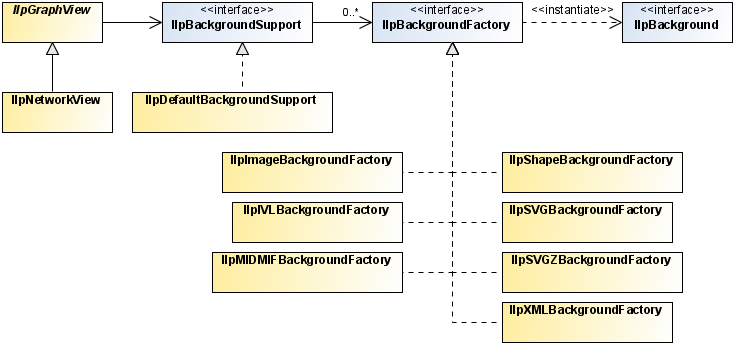
The background API allows you to integrate various types of background in the network and equipment components. It is made up of the following classes (see
Background class relationships and
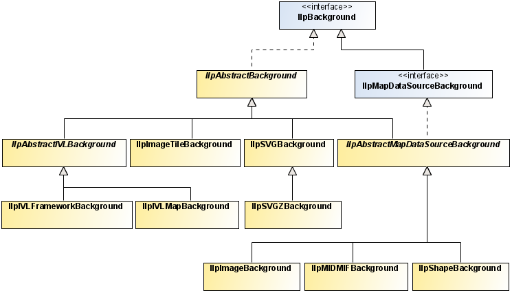
Background support classes for an illustration of the class relationships).
IlpBackground
Backgrounds are implementations of the
IlpBackground interface. This interface is part of the
ilog.cpl.graph.background package where all background classes reside.
An IlpBackground implementation is usually associated with a specific background format. JViews TGO provides implementations of this interface that cover the most used background formats. See the table below for a complete list:
Supported background formats
Background format | Background class | Background file extension |
Scalable Vector Graphics | IlpSVGBackground | SVG |
GZIP Scalable Vector Graphics | IlpSVGZBackground | SVGZ |
Raster Images | IlpImageBackground | GIF, PNG, JPEG and JPG |
Tiled Raster Images | IlpImageTileBackground | GIF, PNG, JPEG and JPG |
ESRI Shape | IlpShapeBackground | SHP, DBF, SHX and IDX |
MID/MIF | IlpMIDMIFBackground | MIF and MID |
JViews Vector Graphics | IlpIVLFrameworkBackground | IVL and ILV |
JViews Vector Graphics | IlpIVLMapBackground | IVL with Map Themes |
If the background format you are interested in is not listed here, please see
Advanced support.
The IlpBackground interface defines two key methods: create and dispose. The method create produces the representation of the background itself; the method dispose disposes of the constructs that compose the representation of the background.
The ultimate representation of an
IlpBackground is made up of instances of
IlvGraphic objects that are part of the Rogue Wave
JViews Framework. These graphics typically reside on one or more instances of
IlvManagerLayer which compose the actual background representation. An
IlpBackground implementation is responsible for appropriately processing the data in a given background format, creating
IlvGraphic instances that appropriately represent the background data and populating one or several
IlvManagerLayer instances with these
IlvGraphic instances. Each
IlvManagerLayer instances is accessible through the
IlpBackground.getManagerLayer method.
IlpAbstractBackground
The
IlpAbstractBackground class is the recommended base class that implements the common methods of the
IlpBackground that should be used when introducing new
IlpBackground types. It implements the
IlvBatchable interface in order to minimize the performance side effects of property changes in a given background instance. For more information on how to use this interface, see the
IlvBatchable and
IlpAbstractBackground API.
IlpBackgroundSupport
Instances of
IlpBackground are managed by an implementation of the
IlpBackgroundSupport interface.
JViews TGO provides a predefined implementation that is used by default, namely the
IlpDefaultBackgroundSupport.
The IlpBackgroundSupport is in charge of providing all background-related functionality that graphic components like IlpNetwork and IlpEquipment may need. For example, it allows you to add, remove, move and reload backgrounds as well as access the added backgrounds and their constructs.
IlpBackgroundSupport is also the entity that handles the lifecycle of IlpBackground instances. It determines when the graphical representation of IlpBackground instances is created or disposed of. The following diagram illustrates the possible states and interactions involved when switching between them:
The following table summarizes the interactions where the IlpBackground API is triggered by the IlpBackgroundSupport:
Interactions between IlpBackground and IlpBackgroundSupport
IlpBackground method | Invoked |
create | • when a background is added to the graphic component • when a background is reloaded in the graphic component (preceded by a call to dispose) |
dispose | • when a background is removed from the graphic component • when a background is reloaded in the graphic component (followed by a call to create) |
Although not optimal, it is nonetheless legal to use a given implementation of IlpBackgroundSupport.moveBackground to remove, then add again a given IlpBackground at the appropriate index in order to move a background. For information on the default implementation of this method, see IlpDefaultBackgroundSupport.moveBackground.
IlpMapDataSourceBackground
The
IlpMapDataSourceBackground is an interface that allows you to integrate additional background formats provided in Rogue Wave JViews Maps via its Map DataSource API. It extends the
IlpBackground interface by defining two additional methods that are necessary to establish the integration with
JViews TGO:
IlpMapDataSourceBackground.createMapDataSource to create the
IlvMapDataSource that will handle the background file and
IlpMapDataSourceBackground.getMapDataSource to provide access to the
IlvMapDataSource of the background.
See
Limitations for limitations related to the functionality provided by the
IlpMapDataSourceBackground.
IlpAbstractMapDataSourceBackground
JViews TGO provides an abstract base class implementation of the
IlpMapDataSourceBackground interface that allows the integration of new
IlvMapDataSource implementations to take place with minor effort. This class is called
IlpAbstractMapDataSourceBackground.
This class handles all the logistics involved in integrating
IlvMapDataSource -based backgrounds within
JViews TGO. It leaves as abstract the
IlpMapDataSourceBackground.createMapDataSource which must be implemented by the concrete type. It introduces a new method,
IlpAbstractMapDataSourceBackground.createRenderer, which returns an
IlvFeatureRenderer that can be used to install a custom feature renderer to be used during the creation of the
IlvGraphic instances for the provided
IlvMapDataSource.
In addition, this type has a utility method,
getMapStyle(), which provides access to the
IlvMapStyle used by the underlying
IlvMapDataSource.
This type is naturally the recommended base type for integrating new implementations of background formats that use the JViews Maps IlvMapDataSource API.
IlpAbstractIVLBackground
JViews TGO uses implementations of
IlpAbstractIVLBackground to integrate backgrounds defined in IVL files. Besides the standard
IlpBackground functionality, this type also allows users to add and remove
IlvManagerLayer instances directly to and from the
IlpAbstractIVLBackground instance through the
IlpAbstractIVLBackground.addManagerLayer and
IlpAbstractIVLBackground.removeManagerLayer, respectively.
The added IlvManagerLayer instances are treated just like another layer that was originated from the source IVL file, meaning that the background properties are propagated to these layers. Thus, the properties of the IlpBackground (like visibility ) are applied to the added layers as the state of the IlpAbstractIVLBackground changes.
See
Limitations for limitations related to the functionality provided by the
IlpAbstractIVLBackground implementations.
There are two implementations of
IlpAbstractIVLBackground :
IlpIVLFrameworkBackground and
IlpIVLMapBackground.
IlpIVLFrameworkBackground should be used to read standard IVL files that contain onlyJViews Framework content. For more information, see IlpIVLFrameworkBackground in the Java™ API Reference Documentation.
IlpIVLMapBackground should be used to read IVL files that contain JViews Maps content. For more information, see IlpIVLMapBackground in the Java API Reference Documentation.
Background class relationships illustrates the background classes.
Background class relationships
Background support classes illustrates the background support classes.
Background support classes
Configuring the background
Backgrounds can be configured at two different levels:
the component level
the individual background level
1. Component backgrounds
As described earlier, you can use the
IlpBackgroundSupport interface to manage backgrounds programmatically. You can add, remove, reload and access backgrounds. See
How to add a background to the network component for a sample on how to add a background to the network component.
You can also specify the precise background configuration through CSS. For more details, see the CSS configuration of backgrounds in
The Backgrounds rule.
2. Individual background
Each IlpBackground instance has a set of predefined properties that can be retrieved or set at runtime through the methods IlpBackground.getProperty or IlpBackground.setProperty. Each IlpBackground implementation defines the properties that are available to customize its behavior and representation. See the IlpBackground interface for general background properties.
You can also specify the precise properties for a given background through CSS. For more details, see the CSS configuration of backgrounds in
The Backgrounds rule.
The following table lists the properties that are available and supported by each IlpBackground implementation:
IlpBackground properties
Name | Type | Default | Sample | Supported backgrounds | Description |
url | String | null | url:”sf-bayarea.png”; | ALL | Defines the URL of the file that contains the background. This is a read-only property. |
visible | boolean | true | visible: ”true” | ALL | Determines whether the background is visible or not. |
loadOnDemand | boolean | false | loadOnDemand: “false” | -Shape (shp) -Image (gif, png and jpg) | Determines whether the background uses load-on-demand or not. |
threaded | boolean | false | threaded: ”true” | -Image (gif, png and jpg) -Image Tile (gif, png and jpg) | Determines whether the internal processing of the background uses a multithreaded approach to improve performance. |
tileHeight | integer | 300 | tileHeight: “100” | Image (gif, png and jpg) | Determines the height, in pixels, of the tile to be created. This property is taken into account only when the loadOnDemand property is set to true. |
tileWidth | integer | 300 | tileWidth: “100” | Image (gif, png and jpg) | Determines the width, in pixels, of the tile to be created. This property is taken into account only when the loadOnDemand property is set to true. |
mapThemed | boolean | true | mapThemed: ”true” | JViews Vector Graphics (ivl) | Determines whether the provided IVL file contains Map Themes. |
Map themes
The background support provided by JViews TGO has become more interactive. Users can now specify a Map Theme to be associated with backgrounds.
A Map Theme is composed of several background-related features such as, but not limited to:
Map Styles - Allows to modify the background graphical representation according to map scale.
Areas of Interest - Bookmarks areas in the view that are of interest.
Coordinate System - The coordinate system that matches the background map.
Display Preferences - Preferences that affect the display of cartographic data as backgrounds and background-related beans.
Map Labeling - Allows the labeling of background data.
These features are provided by the underlying JViews Maps framework and exposed in JViews TGO. You can find more information on each of these features in the JViews Maps Documentation, Using the Map Builder, section Map Themes and Zoom Levels.
Integration
Map Themes integration into JViews TGO is available through the use of IVL background files generated from the JViews Maps Map Builder (more specifically through the use of IlpIVLMapBackground ).
The typical steps for integrating Map Themes created in the Map Builder are:
1. Load the background formats of interest.
2. Edit the various Map features of interest (Map Theme).
3. Save the configured background and its Map Theme as an IVL file.
4. Use this IVL file as a standard background within JViews TGO:
Backgrounds {
background[0]: @+background0;
}
Subobject#background0 {
class: "ilog.cpl.graph.background.css.IlpBackgroundCSSConfiguration";
url: "background/backgroundWithMapTheme.ivl";
mapThemed : true;
}
NOTE After editing the background and its Map Theme in the Map Builder, you can also save the Map Theme onlyin an IVL file. Then you can use the created IVL Map Theme file (which does not contain the background itself) as a standalone background in JViews TGO.
For more information on the JViews Maps Map Builder, see Using the Map Builder in the JViews Maps documentation.
See
Limitations for limitations of the Map Theme functionality.
Background beans
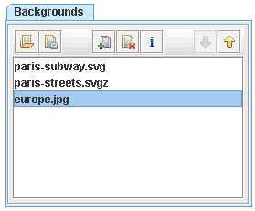
IlpBackgroundPanel
This bean allows you to integrate into your user interface the ability to load, reorder, and save backgrounds for an IlpNetwork or IlpEquipment.
IlpBackgroundPanel Bean
A background located at the top has higher priority (drawing-wise) than the background below it. In the figure above, the europe.jpg background has the lowest priority of all and will be drawn below all other backgrounds. Whereas paris-subway.svg will be drawn on top of all backgrounds (highest priority).
The
IlpBackgroundPanel bean provides the following features:
| Load a CSS file that contains a background configuration |
| Save the current background configuration |
| Add a background to the current configuration |
| Remove the selected background from the current configuration |
| Provide more information on the selected background |
| Move the selected background up |
| Move the selected background down |
You can customize the background files that are filtered by this bean, by setting the getBackgroundExtensions method. You can also specify the default directory where it looks for backgrounds, by using the setDefaultDirectory method. Lastly, you can show or hide both the Add Background and the Remove Background buttons at runtime by using the showAddBackgroundButton and showRemoveBackgroundButton property accessors of IlpBackgroundPanel.
See the IlpBackgroundPanel Java API for additional information.
Some quick facts
When the view is zoomed, the background map is also zoomed.
The objects and the background map do not change positions during zoom operations.
Backgrounds are stacked according to their indices, where the background at index 0 is the bottommost background, that is, it has the lowest priority drawing-wise. However, keep in mind that index i does not necessarily correspond to the
IlvManagerLayer index i, because some backgrounds span over more than one layer.
Advanced support
JViews TGO provides advanced support of the following:
memory management
configuring backgrounds through XML
integration of background formats not supported natively
Memory management
Some of the IlpBackground implementations allow you to configure the policy used to handle the management of the resources needed to represent its format.
This is the case in particular with the
IlpImageBackground which leverages the advanced performance features provided by JViews Maps. More specifically, it takes advantage of the
IlvRasterMappedBuffer which allows you to specify the memory management policy used to handle the rasters that ultimately represent the backgrounds.
By default, JViews TGO enforces the in-memory policy which stores the resources in memory. But you can also take advantage of the disk-mapped policy which stores pixel information on disk-mapped memory.
For more details on this topic, see:
The
Rogue Wave JViews Maps Documentation,
Programming with JViews Maps, section
Raster Image Management.
The
IlvRasterMappedBuffer Java API.
XML background format
In addition to the natively supported background formats (see
Supported background formats ),
JViews TGO also provides the ability to configure backgrounds via XML.
The XML format allows you to configure one or more background files and specify some of the properties that each background uses to configure itself. This format is typically used if you need an image tile background and need to specify its configuration statically. Image tile backgrounds consist of a rectangular array of JPG, GIF, or PNG files, each with a filename denoting the column number and the row number. For a sample of how to make use of this format and configure an image tile background, see
How to specify a tiled image background using the XML format.
NOTE >> The XML format does not support all the parameters, such as offsets and built-in projections, that a given background may internally use.
Unless you have specific needs, the recommended way to configure your backgrounds is through CSS which allows nearly any type of customization.
Integration of unsupported background formats
If you want to use of a background format that is not supported natively by JViews TGO (for example, TIGER Line maps), the recommended approach is to check if this format is supported by the underlying JViews Maps product that JViews TGO makes use of. If this map format is supported by JViews Maps, then you should follow these steps:
1. Use the JViews Maps Map Builder to load and customize the map as needed.
2. Export the map as an IVL file.
3. Use this IVL file as an IVL background file that contains JViews Maps content in JViews TGO, as described in
Integration.
For more information on the JViews Maps Map Builder, see Using the Map Builder in the JViews Maps documentation.
If the map format is supported neither by JViews TGO nor by JViews Maps, then it is recommended to export the unsupported format into one of the formats supported by JViews Framework, JViews Maps or JViews TGO, so that the standard or above integration can take place.
Limitations
The following table lists the limitations of backgrounds in JViews TGO:
Background limitations
Area | Description |
Map Themes - Multiple backgrounds | Loading a background that contains a map theme may overwrite some or all of the map theme settings of a previously loaded background. The recommended approach will be to: 1. Load all the backgrounds of interest in the JViews Maps Map Builder. 2. Customize the map theme of all these backgrounds. 3. Save the map theme as a whole (as opposed to individually). 4. Load the global map theme as a standard IVL background. |
IlpMapDataSourceBackground | Access to the IlvCoordinateSystem of an IlvMapDataSource from an IlpMapDataSourceBackground is read-only. If you set the coordinate system of the IlvMapDataSource for a given IlpMapDataSourceBackground through the method IlvMapDataSource.setCoordinateSystem(), it will not take effect because the IlvMapDataSource is recreated during a background reload. If you need to customize the map data source with a custom IlvCoordinateSystem, the recommended approach is to overwrite the IlpAbstractMapDataSource.createDataSource method to return an IlvMapDataSource that already has the IlvCoordinateSystem of interest set on it. |
IlpAbstractIVLBackground | When you add IlvManagerLayer instances manually to an IlpAbstractIVLBackground, these instances will not be restored during a background reload. If reload support is required, it is recommended to create an additional IlpAbstractIVLBackground that points to an IVL file containing the additional graphics, or to add again the additional IlvManagerLayer instances after the background has been reloaded. |
How to add a background map in MIF format
URL url = context.getURLAccessService().getFileLocation("world.mif");
networkComponent.addBackgroundURL(url);
How to add a background to the network component
IlpNetwok network = …;
URL backgroundURL = context.getURLAccessService().getFileLocation("backgrounds/
world.png");
How to specify a tiled image background using the XML format
<?xml version="1.0" encoding="UTF-8"?>
<background
xmlns:xsi="http://www.w3.org/2001/XMLSchema-instance"
xsi:noNamespaceSchemaLocation="ilog/cpl/schema/background.xsd"
type="ImageTile">
<property name="pattern">jpp%c%r.jpg</property>
<property name="tileWidth">400</property>
<property name="tileHeight"400</property>
</background>
How to add an IVL background to the underlying IlvManager
The appropriate approach is to use an IlpAbstractIVLBackground, which gives you direct access to the underlying IlvManager that hosts the network (or equipment) component. If this approach does not satisfy your needs, you can (although this is not advised):
1. Obtain the IlpNetwork or ( IlpEquipment ) underlying IlvManager by calling network.getView().getManagerView().getManager()
2. Make sure that the needed number of IlvManagerLayer instances is inserted in this IlvManager (so that your background does not corrupt any of the existing IlvManagerLayer instances).
You can add more IlvManagerLayer instances by calling IlvManager.addLayer(0)
3. Call IlvManager.read to read the IVL file.
How to find out the georeferencing configuration needed for my IlpGeographicPositionconverter
If your background is georeferenced, you will likely be using several advanced Map background settings that are required when configuring the IlpGeographicPositionConverter.
These settings can typically be found in the IlvCoordinateSystem associated with a given background.
If you use an
IlpMapDataSourceBackground, you can access its
IlvMapDataSource and from there you can find the
IlvCoordinateSystem.
If you use a non
IlpMapDataSourceBackground, the information is typically configured manually by setting it explicitly on the underlying
IlvManager or indirectly through a Map Theme (in an IVL file). Either way, you can access the
IlvCoordinateSystem through the call
IlvCoordinateSystemProperty.getCoordinateSystem().
Note that if you have different coordinate systems for which you want to find out an IlvMathTransform, you can use an IlvCoordinateTransformation.
Lastly, note that the different types of IlvCoordinateSystem provide different types of settings. For example, an IlvProjectedCoordinateSystem provides access to a possibly needed IlvProjection. So assuming that the background map has an IlvProjectedCoordinateSystem, to find out the IlvProjection used by it, you can do the following:
IlpMapDatasourceBackground background = …;
IlvCoordinateSystem coordinateSystem =
background.getMapDataSource().getCoordinateSystem();
if(coordinateSystem instanceof IlvProjectedCoordinateSystem) {
IlvProjectedCoordinateSystem projectedCoordinateSystem =
(IlvProjectedCoordinateSystem)coordinateSystem;
IlvProjection projection = projectedCoordinateSystem.getProjection()
…
}
Filtering
The network component allows you to filter the nodes that are displayed. To do so, attach an instance of
IlpFilter to the network component by using the method
setFilter. The
accept() method of the filter object will be invoked whenever the network is prompted to display an
IlpObject. If the method returns
false, the object will not be shown in the network. In the same way, an object will not be shown if its parent is not displayed.
For example, write the following code to show only objects of the class
IltNetworkElement.
How to filter objects to be shown in the network component
IlpNetwork network = // ...
// Create a new IlpFilter instance
IlpFilter filter = new IlpFilter(){
// This method is called for every object in the data source
public boolean accept (Object object){
IlpObject ilpObject = (IlpObject)object;
IlpClass clz = ilpObject.getIlpClass();
// Check if the class == IltNetworkElement
return clz.equals(IltNetworkElement.GetIlpClass());
}
// Set the filter to the network
network.setFilter(filter);
All the objects are refiltered whenever a new filter is set. If the filter is null (which is the default), all the objects under the root nodes will be displayed.
To retrieve the active filter, use the method
getFilter.
NOTE The filtering takes actually place at the adapter level.
To see how to configure filtering through CSS, refer to
The Adapter rule.
Accepted and excluded classes
You can specify the business objects that will be represented or not in the network component depending on their business classes. To do so, you need to specify the business classes to be accepted or excluded using methods
setAcceptedClasses or
setExcludedClasses in the network component adapter. To retrieve the adapter, use the
getAdapter method. The adapter must be an instance of a subclass of
IlpAbstractNodeAdapter. By default, business objects of the class
IltAlarm are excluded from the network component, so that alarm objects in the data source are only used to compute the alarms present in a given managed entity instead of being graphically represented in the view.
How to specify excluded classes in the network component
You can specify that business objects from specific business classes are not represented in the network component. You can do that using the API,
setExcludedClasses method, or using CSS.
The following example shows you how to prevent objects from business classes
IltAlarm and
IltLed to be represented:
Adapter {
excludedClasses[0]: "ilog.tgo.model.IltAlarm";
excludedClasses[1]: "ilog.tgo.model.IltLed";
}
How to specify an accepted class in the network component
By default, all business classes, except
IltAlarm, are accepted by the network component. If you want to specify exactly which business classes to represent, you should combine the list of excluded and accepted classes, so that you exclude all business classes except those that are marked in the accepted class list.
In the following example, the network component is configured in a way that it graphically represents only business objects from the class
IltNetworkElement.
Adapter {
excludedClasses[0]: "ilog.tgo.model.IltAlarm";
excludedClasses[0]: "ilog.tgo.model.IltObject";
acceptedClasses[0]: "ilog.tgo.model.IltNetworkElement";
}
NOTE The filtering that is performed through the use of the accepted and excluded class lists takes actually place at the adapter level.
To see how to configure excluded and accepted classes through CSS, refer to
The Adapter rule.
Setting a list of origins
By default, all the objects in the data source that do not have a parent are treated as root nodes by the network component. However, you can explicitly select the root nodes to be displayed through the adapter that forms a bridge between the data source and the network component. To retrieve the adapter, use the
getAdapter method. The adapter must be an instance of a subclass of
IlpAbstractNodeAdapter.
The root nodes can be changed by modifying the list of
origins for the adapter. These origins are set and retrieved as
IlpObject identifiers. The network adapter has two options: either the origins are represented as root nodes, or they are hidden and their child objects are represented as root nodes.
The method getOrigins allows you to get the list of current origins. The method isShowingOrigin indicates whether the origins themselves or their child objects are represented as root nodes. By default, the list of origins is empty and the origins are not shown, which means that all objects without a parent are shown as root nodes. Thus, the entire contents of the data source are displayed in the network.
NOTE The origins are specified using identifiers, not the
IlpObject instances. You can retrieve the identifier of an
IlpObject with the
getIdentifier method of the object.
To change the list of origins, use the setOrigins method. This method takes a list of business object identifiers as its first parameter. Its second parameter is a Boolean flag that indicates whether or not the origins themselves should be shown as root nodes.
Calling this method with an empty list and the second parameter set to true empties the network:
setOrigins(Collections.EMPTY_LIST, true);
Calling the method with an empty list and the second parameter set to false restores the default; that is, all the objects in the data source are shown:
setOrigins(Collections.EMPTY_LIST, false);
How to show an object as the root node of a network
To show only a given
IlpObject as the root node of a network, use the following code:
IlpNetwork network = ....;
IlpObject originObject = .....;
java.util.List originList = new ArrayList();
originList.add(originObject.getIdentifier());
network.getAdapter().setOrigins(originList, true);
See the
IlpAbstractHierarchyAdapter class for additional methods to help you manage origins.
To see how to configure origins through CSS, refer to
The Adapter rule.
Node factory
The network adapter converts business objects retrieved from the associated data source into instances of
IlpNetworkNode. The new representation objects are created by a representation object factory. The network adapter uses by default the
IlpDefaultNetworkNodeFactory that creates representation objects of type
IlpDefaultNetworkNode.
To know how to configure a network node factory through CSS, refer to
The Adapter rule.
Link factory
As the network node factory transforms business objects into representation objects, the link factory transforms business objects that are links into representation objects that are instances of
IlpNetworkLink. The network adapter uses by default the
IlpDefaultNetworkLinkFactory that creates representation objects of type
IlpDefaultNetworkLink.
To see how to configure a network link factory through CSS, refer to
The Adapter rule.
Expansion strategy
The network adapter uses an expansion strategy to identify whether objects should be loaded or not in the network model. The expansion strategy defines how an object is going to behave when it is expanded, for example, when the user opens a network node by double-clicking or by using the network expansion handles. The expansion strategy indicates whether load on demand is implemented and provides methods to load and release child nodes.
The network adapter uses an
expansion strategy factory to decide the expansion strategy to apply to a network node when it is created by the adapter. The default expansion strategy factory implementation,
IlpDefaultNodeExpansionStrategyFactory, checks the property
"expansion" of each business object in the cascading style sheet loaded in the component to identify the expansion strategy to use.
The default network expansion strategy factory supports three types of expansion strategies:
IN_PLACE : loads the child objects immediately in the network model. In this expansion strategy, nodes are considered as parent nodes only when they have containment relationships defined in the attached data source, through the
IlpContainer interface. The child objects should already be loaded in the data source and should be visible according to the data source filter, if there is one defined.
IN_PLACE_MINIMAL_LOADING : loads the child objects on demand in the network model, that is, as the user expands the parent nodes. All nodes with this expansion strategy are considered as possible parent nodes, and therefore are represented with an expansion icon. If the node does not contain child objects, the expansion icon will disappear when the expansion is executed for the first time.
NO_EXPANSION : expansion is not supported by the node.
See
Customizing the expansion of business objects in the
Styling documentation for information on how to customize the business object expansion type, which is defined by the property
expansion.
The expansion strategy factory can be customized for the adapter either through CSS or through the API.
Copyright © 2018, Rogue Wave Software, Inc. All Rights Reserved.