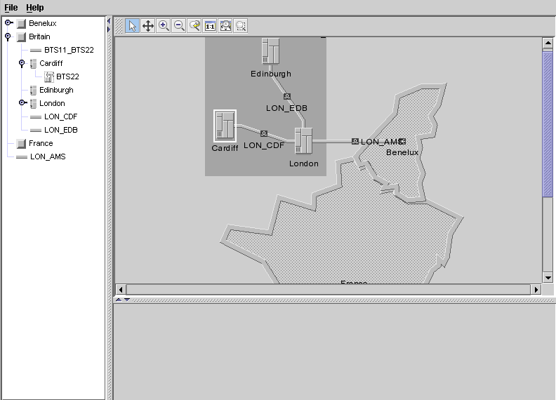
Shows you how to create a tree component to show the containment
hierarchy. The data for this part of the tutorial is in the file <installdir>/tutorials/gettingStarted/data/elements.xml.
To allow the tree component to function, you must create a tree
component and connect it to a data source. This example uses the
same data source that was created for the network component to show
the same data in the tree and the network. A new XML data file is
read into the data source. This file includes the child elements to
be contained under the top level objects (
Britain
and
Benelux
) read in Step 1. See Creating a basic network component.
You must also add the tree component to the
container or frame.
This part of the code is referred to as Step
2:
void step2() throws Exception {
To do Step 2:
- Create the tree component.
treeComponent = new IlpTree();
- Connect the data source
mainDataSourceto the tree component.treeComponent.setDataSource(mainDataSource);
The data source shows the tree with containment by default in line with the data that will be read in from the XML file. - Read in the data to the data source from the file
elements.xml.mainDataSource.parse("elements.xml");The data concerns named Base Station Controller (BSC) and Base Station Transceiver (BTS) objects and a link between the BTS subnodes. This data is added to the main data in the data source.NoteHere top-level BTS nodes only are created. JViews TGO also supports a more complete representation of BTS nodes and their antennas through the class IltBTS.The BSC network elements,CardiffandLondon, are both contained underBritain. The BTSs are child objects of the BSCs.Each node object belongs to the business class IltNetworkElement, which has the following attributes among others:nametypefamilyfunctionpositionThe position is not meaningful for the tree, but it is used to display the elements in the network component. The tutorial uses pixel (x,y) coordinates, as supported by the Java™ class IlpPoint. You can also give geographic positions as latitude and longitude values through the class IlpGeographicPosition. In this case, you need to provide a corresponding IlpGeographicPositionConverter to the network component. See Creating a network component: a sample in the Graphic Components documentation for details.
The following is an example of how a node is described in an JViews TGO XML data file:<addObject id="London"> <class>ilog.tgo.model.IltNetworkElement</class> <parent>Britain</parent> <attribute name="name">London</attribute> <attribute name="type">BSC_Image</attribute> <attribute name="position"> javaClass="ilog.cpl.graphic.IlpPoint"> <x>269.0</x> <y>149.0</y> </attribute> </addObject>The links belong to the class IltLink. They are defined in terms of their start and end nodes. The links are named by their start and end node IDs. The start node is defined within a<from>element and the end node is defined within a<to>element. The file provides values for the following link attributes:namemediaThe media defines the material of the link, such as fiber optic.
The following is an example of how a link is described in an JViews TGO XML data file:<addObject id="BTS11_BTS22"> <class>ilog.tgo.model.IltLink</class> <parent>Britain</parent> <attribute name="name">BTS11_BTS22</attribute> <link> <from>BTS11</from> <to>BTS22</to> </link> <attribute name="media">Fiber</attribute> </addObject> - Add the tree component to the container or frame.
  treeArea.add(treeComponent,BorderLayout.CENTER);
}
This causes the tree component to be displayed in the corresponding area of the main frame.
The sample with the tree component should
look as shown in the following figure.
