Contact points
Describes the default contact points on a node for attaching links and how to define link connectors and pins to specify different contact points.

Describes the default contact points on a node for attaching links.
Describes how to define link connectors.
Explains the role of pins and how to use them, with an example.
Describes other link connectors that do not use pins.
Default contact points
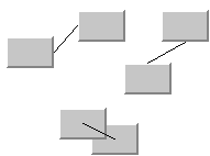
When a link is created between two nodes, it is attached to the default contact point of each node. Each node has five default contact points, one at the center of each side of its bounding rectangle and one at the center of the bounding rectangle. The contact point actually used depends on the location and size of the origin and destination node. The following are examples of connections:
Examples of node connections
Using link connectors
The grapher provides a way to specify the contact points you need on a graphic object. This is done by using
link connectors, which are subclasses of the class
IlvLinkConnector,
The class
IlvLinkConnectoris dedicated to the computation of the connection points of links. Subclasses of this abstract class can be used to obtain contact points other than the default ones. An
IlvLinkConnector is associated with a node. The implementation of the method
getConnectionPoint decides where the connection point of a link (provided as an argument) should be located.
An instance of
IlvLinkConnector can be specified for each node of a grapher. To do this, simply create it using the constructor
IlvLinkConnector or use the method
attach. Notice that the same instance of link connector cannot be shared by several nodes.
A link connector specified for a node controls the connection points of all the links incident to this node. If you need the connection points of the incident links not to all be computed in the same way (that is, by the same link connector), you can specify a link connector individually for each extremity of each link. To do this, simply create it using the constructor
IlvLinkConnector(ilog.views.IlvLinkImage, boolean)
or use the method
attach(IlvLinkImage, boolean, boolean).
To get the instance of link connector actually used to compute the contact point of a given link, use the static method
Get.
Using pins
Each link is attached to what is called a pin. Each pin describes the position of a contact point on a node.
The class
IlvPinLinkConnector, which is a subclass of the class
IlvLinkConnector, manages the link connections to a node. An instance of the class
IlvPinLinkConnector may be installed on a graphic object. This instance holds a set of pins.
When you create an
IlvPinLinkConnector instance, it is empty and does not contain any pins. You must provide a set of pins describing the position of the contact points that you need. The pins are defined by the class
IlvGrapherPin. This class is an abstract class because its
getPosition method is an abstract method. For this reason, you must first create a subclass of the
IlvGrapherPin class. Specifying an implementation to the
getPosition method enables you to indicate the position of the
grapher pin. The signature of this method follows:
IlvPoint getPosition(IlvTransformer t)
The position of the pin depends on the transformer used to draw the node. This transformer is passed to the getPosition method. To compute the position of the pin, you may need to know the position of the node. For its position, use:
IlvGraphic getNode()
You may also decide to allow or inhibit the connection of a certain type of link to this pin. To do so, you overwrite the allow method of your pin, which is called when you create a link with an interactor:
boolean allow(Object oClass, Object dClass, Object linkOrClass, boolean origin)
The interactor is authorized to highlight only the specified pin based on the result of this method.
Once the pin classes are created, you must add the pins to the previously created instance of IlvPinLinkConnector using the following method:
void addPin(IlvGrapherPin pin)
Example: Defining your connection points
This example defines two classes of pins:
The class
InPin that allows links to go to the node.
The class
OutPin that allows links to come from the node.
The pins of class InPin are placed on the left border of the object and the pins of type OutPin on the right border.
The classes are:
final class InPin extends IlvGrapherPin
{
static final int numberOfPins = 5;
int index;
public InPin(IlvPinLinkConnector connector, int index)
{
super(connector);
this.index = index;
}
protected boolean allow(Object orig, Object dest,
Object linkOrClass,
boolean origin)
{
return !origin;
}
public IlvPoint getPosition(IlvTransformer t)
{
IlvRect bbox = getNode().boundingBox(null);
IlvPoint p = new IlvPoint(bbox.x,
bbox.y+(bbox.height/(numberOfPins+1)*
(index+1));
if (t != null) t.apply(p);
return p;
}
}
In this example, five instances of InPin will be created. Each pin has an index giving its position on the node. The getPosition method returns the position of the pin on the left side of the node according to its index. The allow method returns true only for links going to this pin (parameter origin is false ). The OutPin class is very similar:
final class OutPin extends IlvGrapherPin
{
static final int numberOfPins = 5;
int index;
public OutPin(IlvPinLinkConnector connector, int index)
{
super(connector);
this.index = index;
}
protected boolean allow(Object orig, Object dest,
Object linkOrClass, boolean origin)
{
return origin;
}
public IlvPoint getPosition(IlvTransformer t)
{
IlvRect bbox = getNode().boundingBox(null);
IlvPoint p = new IlvPoint(bbox.x+ bbox.width,
bbox.y+(bbox.height/
(numberOfPins+1))*(index+1));
if (t != null) t.apply(p);
return p;
}
}
The pins are located on the right side and only allow links leaving the node.
If node is a graphic object, the method that adds the pins to the node is:
grapher.addNode(node, 1, false);
IlvPinLinkConnector lc = new IlvPinLinkConnector(node);
for (int i = 0; i < 5; i++) {
new InPin(lc, i);
new OutPin(lc, i);
}
If you want to connect a link to a particular pin, use the method connectLink of the class IlvPinLinkConnector:
public void connectLink(IlvLinkImage link, IlvGrapherPin pin, boolean origin)
Other link connectors
Other link connectors are available as follows:
A CenterLinkConnector
IlvFreeLinkConnector to position the link relatively to the node. Any point can be used as the connection point. The connection points are preserved with respect to the bounding box when the node is translated, or when it grows or shrinks.
A FreeLinkConnector
IlvClippingLinkConnector to clip the link at the node border. Like the free link connector, this connector attaches the link to any point inside the node and preserves this attachment point relative to the bounding box of the node. If the node moves, grows, or shrinks, the attachment point moves proportionally. However, unlike the free link connector, the link segment towards the attachment point is clipped at the border of the node by using the method
getIntersectionWithOutline. This is useful for arrowheads when the shape of the node is nonrectangular.
A ClippingLinkConnector
Copyright © 2018, Rogue Wave Software, Inc. All Rights Reserved.