Bus layout (BL)
Describes the
Bus Layout algorithm (class
IlvBusLayout from the package
ilog.views.graphlayout.bus).

Gives a sample of the Bus Layout (BL) and explains where it is used.
Lists the features of the layout.
Describes the Bus Layout algorithm and gives samples of the specification.
Lists the generic features and parameters of the Bus Layout (BL).
Lists the specific parameters of the Bus Layout (BL).
BL - sample
The following figure shows a sample drawing produced with the Bus Layout (BL).
Bus topology produced with the Bus Layout
What types of graphs suit the BL?
Bus network topologies (a set of nodes connected to a bus object)
Application domains for the BL
Application domains of the Bus Layout include:
Telecom and networking (LAN diagrams)
Electrical engineering (circuit block diagrams)
Industrial engineering (equipment/resource control charts)
Features of the BL
Displays bus topologies.
Takes into account the size of the nodes so that no overlapping occurs.
Provides several ordering, alignment, and flow direction options.
Allows easy customization of the dimensional parameters.
The BL algorithm
Bus topology is well known in network management and telecommunications fields. The Bus Layout class can display these topologies nicely. It represents the “bus” as a “serpent” polyline. The width of the “serpent” is user-defined (via the width of the layout region parameter) and the height is computed so that enough space is available for all the nodes.
BL - CSS Sample
BL example
In CSS
Below is a sample CSS specification using the Bus Layout algorithm. Since the Bus Layout places nodes and reshapes the links, it is usually not necessary to specify an additional link layout in CSS. The CSS specification can be loaded as a style file into an application that uses the
IlvDiagrammer class (see
Graph layout in Rogue Wave JViews Diagrammer.
SDM {
GraphLayout : "true";
LinkLayout : "false";
}
GraphLayout {
graphLayout : "Bus";
flowDirection : "LEFT_TO_RIGHT";
nodeComparator: "DESCENDING_HEIGHT";
}
To be laid out by the Bus Layout, the graph needs to contain a bus node connected with links to several other nodes. When you specify the Bus Layout in CSS, the data model must respect this condition. Moreover, the CSS statements of the graphic objects used for the nodes must specify a graphic object implementing the
IlvPolyPointsInterface to allow the Bus Layout to discover the bus node automatically when it is not explicitly specified (for details, see
Bus node (BL)). Typically, you can do this by specifying a node rule in which the selector uses an attribute of the node in the data model that identifies the bus node.
In Java™
The following code sample uses the
IlvBusLayout class. This code sample shows how to perform a Bus Layout on a grapher directly without using a diagram component or any style sheet:
...
import ilog.views.*;
import ilog.views.graphic.*;
import ilog.views.graphlayout.*;
import ilog.views.graphlayout.bus.*;
...
IlvGrapher grapher = new IlvGrapher();
IlvManagerView view = new IlvManagerView(grapher);
... /* Fill in the grapher with nodes and links here */
/* Create the bus node; the number of points and
the coordinates are not important */
IlvPoint[] points = {new IlvPoint(10, 10)};
IlvPolyline bus = new IlvPolyline(points);
grapher.addNode(bus, false);
... /* Fill in the grapher with links between each node
and the bus here */
IlvBusLayout layout = new IlvBusLayout();
layout.attach(grapher);
/* Specify the bus node */
layout.setBus(bus);
try {
IlvGraphLayoutReport layoutReport = layout.performLayout();
int code = layoutReport.getCode();
System.out.println("Layout completed (" +
layoutReport.codeToString(code) + ")");
}
catch (IlvGraphLayoutException e) {
System.err.println(e.getMessage());
}
Generic features and parameters of the BL
The
IlvBusLayout class supports the following generic parameters defined in the
IlvGraphLayout class (see
Base class parameters and features):
Extra feature for JViews Diagrammer:
The following sections describe the particular way in which these parameters are used by this subclass.
Allowed time (BL)
The layout algorithm stops if the allowed time setting has elapsed. (For a description of this layout parameter in the
IlvGraphLayout class, see
Allowed time.) The result code in the layout report is
IlvGraphLayoutReport.STOPPED_AND_INVALID.
Layout of connected components (BL)
The layout algorithm can use the generic mechanism to layout connected components. (For more information about this mechanism, see
Layout of connected components.)
Layout region (BL)
The layout algorithm uses the layout region setting (either your own or the default setting) to control the size and the position of the graph drawing. All three ways to specify the layout region are available for this subclass (See
Layout region.)
The size of the layout is chosen with respect to the layout region (see
Dimensional parameters for the Bus Layout algorithm). The height of the layout region is not taken into account. The height of the layout will be smaller or larger, depending on the number of nodes, the size of the nodes, and the other specified parameters.
Link clipping (BL)
The layout algorithm can use a link clip interface to clip the end points of a link. (See
Link clipping.)
This is useful if the nodes have a nonrectangular shape such as a triangle, rhombus, or circle. If no link clip interface is used, the links are normally connected to the bounding boxes of the nodes, not to the border of the node shapes. See
Using a link clipping interface with the Bus Layout for details of the link clipping mechanism.
Preserve fixed links (BL)
The layout algorithm does not reshape the links that are specified as fixed. (See
Preserve fixed links.)
Preserve fixed nodes (BL)
The layout algorithm does not move the nodes that are specified as fixed. (See
Preserve fixed nodes.)
Save parameters to named properties (BL)
The layout algorithm can save its layout parameters into named properties. This can be used to save layout parameters to
.ivl files. (For a detailed description of this feature, see
Save parameters to named properties and
Saving layout parameters and preferred layouts.)
Stop immediately (BL)
The layout algorithm stops after cleanup if the method
stopImmediately is called. (For a description of this method in the
IlvGraphLayout class, see
Stop immediately.) If the layout stops early because the allowed time has elapsed, the result code in the layout report is
IlvGraphLayoutReport.STOPPED_AND_INVALID.
Specific parameters of the BL
The following parameters are specific to the
IlvBusLayout class.
Order parameter (BL)
The order parameter specifies how to arrange the nodes.
Example of specifying node ordering option (BL algorithm)
To specify the ordering option for the nodes:
In CSS
Add to the GraphLayout section:
nodeComparator : "DESCENDING_HEIGHT";
In Java™
Use the method:
void setNodeComparator(Comparator comparator)
The valid values for comparator are:
IlvBusLayout.DESCENDING_HEIGHT The nodes are ordered in the descending order of their height.
IlvBusLayout.ASCENDING_HEIGHT The nodes are ordered in the ascending order of their height.
IlvBusLayout.DESCENDING_WIDTH The nodes are ordered in the descending order of their width.
IlvBusLayout.ASCENDING_WIDTH The nodes are ordered in the ascending order of their width.
IlvBusLayout.DESCENDING_AREA The nodes are ordered in the descending order of their area.
IlvBusLayout.ASCENDING_AREA The nodes are ordered in the ascending order of their area.
IlvBusLayout.ASCENDING_INDEX The nodes are ordered in the ascending order of their index (see
setIndex).
IlvBusLayout.DESCENDING_INDEX The nodes are ordered in the descending order of their index (see
setIndex).
null The nodes are ordered in an arbitrary way.
Any other implementation of the Comparator interface.
The nodes are ordered according to this custom comparator.
The default is null.
The ordering of the nodes starts at the upper-left corner of the bus.
Note that in incremental mode (see
setIncrementalMode) or when nodes are fixed (see
setFixed), the order is not guaranteed to obey the comparator, because it competes with the other constraints.
More about the ASCENDING_INDEX and DESCENDING_INDEX options (BL)
These options allow you to specify the order of the nodes according to a user-defined index value specified for each node. If this option is chosen, the algorithm sorts the nodes in ascending order according to their index values.
Example of specifying index options (BL algorithm)
The index is an integer value associated with a node. To specify the index:
In CSS
Write a rule to select the node:
#node1 {
Index: "3";
}
In Java
Use the method:
void setIndex(Object node, int index)
The values of the indices cannot be negative. To obtain the current index of a node, use the method:
int getIndex(Object node)
If no index is specified for the node, the value IlvBusLayout.NO_INDEX is returned.
The following table shows the ordering options for the Bus Layout algorithm.
Examples of ordering options for the nodes for the Bus Layout algorithm
Ordering | Layout |
No order | |
DESCENDING_HEIGHT | |
ASCENDING_INDEX | |
Bus node (BL)
To represent bus topologies, the algorithm reshapes a special node, called the “bus node”, and gives it a “serpent” form. This bus node must be an instance of the
IlvPolyPointsInterface class. Usually, you use its subclass
IlvPolyline. Before performing the layout, you must create this object and add it to the grapher as a node.
(The number of points in the object you create is not important.) Then, you must specify the node as “bus node” using the method:
void setBus(IlvPolyPointsInterface bus)
If none is specified, the Bus layout automatically tries to find an appropriate node that can be used as bus object.
The bus object must implement the interface
IlvPolyPointsInterface and it must allow the insertion and removal of points (see the methods
allowsPointInsertion and
allowsPointRemoval defined by the interface). The initial number of points is not significant.
When a bus object is specified or automatically discovered in an
IlvGrapher, the appropriate link connector is automatically installed on it. By default, the link connector is of type
IlvBusLinkConnector.
Usually, the class
IlvPolyline is used for the bus object. The bus object must be added to the
IlvGrapher as a node (using the method
addNode). The links between the bus and the nodes connected to the bus must be created before performing the layout. (See the Java code provided in
BL - CSS Sample.)
Link style (BL)
When the layout algorithm moves the nodes,
straight-line links (such as instances of
IlvLinkImage) will automatically “follow” the new positions of their end nodes. If the grapher contains other types of links (for example,
IlvPolylineLinkImage or
IlvSplineLinkImage), the shape of the link may not be appropriate because the intermediate points of the link will not be moved. In this case, you can specify that the layout algorithm automatically removes all the intermediate points of the links (if any).
Example of specifying BL to automatically remove all intermediate points of the link (BL algorithm)
To specify that the layout algorithm automatically removes all the intermediate points of the links (if any):
In CSS
Add to the GraphLayout section:
linkStyle : "STRAIGHT_LINE_STYLE";
In Java
Use the method:
void setLinkStyle(int style)
The valid values for style are:
IlvBusLayout.NO_RESHAPE_STYLE None of the links are reshaped in any manner.
IlvBusLayout.STRAIGHT_LINE_STYLE All the intermediate points of the links (if any) are removed. This is the default value.
Flow direction (BL)
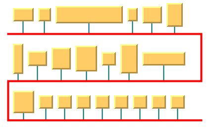
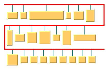
The flow direction options control the horizontal alignment of each row (bus level) with respect to the left and right sides of the layout region. The rows can be either all left-aligned on the left border of the layout region or can alternate between left and right alignment.
Bus layout with left-to-right flow direction
Bus layout with alternating flow direction
Example of setting the flow direction (BL algorithm)
To set the flow direction:
In CSS
Add to the GraphLayout section:
flowDirection : "ALTERNATE";
In Java
Use the method:
void setFlowDirection(int direction);
The valid values for direction are:
IlvBusLayout.LEFT_TO_RIGHT (the default)
All the rows (bus levels) are left-aligned.
IlvBusLayout.ALTERNATE The even rows (bus levels) are left-aligned and the odd rows are right-aligned.
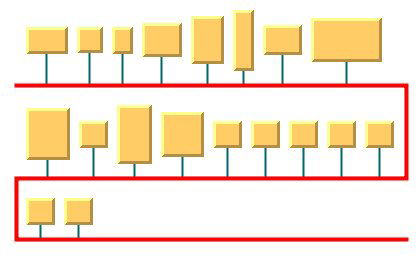
Maximum number of nodes per level (BL)
By default, the layout places as many nodes on each level as possible given the size of the nodes and the dimensional parameters (layout region and margins). If needed, the layout can additionally respect a specified maximum number of nodes per level (see
Bus width with adjusting disabled and bounded number of nodes per level and
Bus width with adjusting enabled and bounded number of nodes per level).
Example of setting the maximum number of nodes per level (BL algorithm)
To set the maximum number of nodes per level:
In CSS
Add to the GraphLayout section:
maxNumberOfNodesPerLevel : "5";
In Java
Use the method:
void setMaxNumberOfNodesPerLevel(int nNodes);
The default value is Integer.MAX_VALUE. This means that the number of nodes placed in each level is only bounded by the size of the nodes and the dimensional parameters. The specified value must be at least 1.
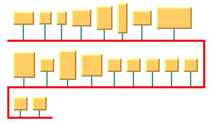
Bus width adjusting (BL)
By default, the width of the bus object, that is the difference between the maximum and minimum x-coordinates, depends on the width of the layout region and the other dimensional parameters (see
Dimensional parameters for the Bus Layout algorithm). Optionally, the width of the bus object can be automatically adjusted to the total width of the nodes, plus the offsets and the margins. This option can be particularly useful in conjunction with the customization of the maximum number of nodes per level (see
Maximum number of nodes per level (BL)).
Bus width with adjusting disabled and bounded number of nodes per level
Bus width with adjusting enabled and bounded number of nodes per level
Example of enabling/disabling the bus width adjustment (BL algorithm)
To enable or disable bus width adjusting:
In CSS
Add to the graph layout section:
busWidthAdjustingEnabled: "true";
In Java
Use the method:
void setBusWidthAdjustingEnabled(boolean enable);
The bus width adjusting is disabled by default.
Bus line extremity adjusting (BL)
If necessary, the bus line can be adjusted to stop where the nodes stop (plus the margins). This can make a difference when there is only one horizontal bus line, or when the flow direction is ALTERNATE.
Bus Layout with bus line extremity disabled
Bus Layout with bus line extremity enabled
Example of enabling/disabling the bus line extremity adjustment (BL algorithm)
To enable or disable the adjustment of the bus line extremity:
In CSS
Add to the graph layout section:
busLineExtremityAdjustingEnabled: "true";
In Java
Use the method:
void setBusLineExtremityAdjustingEnabled (boolean enable);
The adjustment of the bus line extremity is disabled by default.
Alignment parameters (BL)
The alignment options control how a node is placed above its row (bus level). The alignment can be set globally, in which case all nodes are aligned in the same way, or locally on each node, with the result that different alignments occur in the same drawing.
Global alignment parameters
Example of setting global alignment (BL algorithm)
To set the global alignment:
In CSS
Add to the GraphLayout section:
globalVerticalAlignment : "TOP";
In Java
Use the method:
void setGlobalVerticalAlignment(int alignment);
The valid values for alignment are:
IlvBusLayout.CENTER (the default)
The node is vertically centered over its row (bus level).
IlvBusLayout.TOP The node is vertically aligned on the top of its row (bus level).
IlvBusLayout.BOTTOM The node is vertically aligned on the bottom of its row (bus level).
IlvBusLayout.MIXED Each node can have a different alignment. The alignment of each individual node can be set with the result that different alignments can occur in the same graph.
Bus Layout with center vertical alignment
Bus Layout with top vertical alignment
Bus Layout with bottom vertical alignment
Alignment of individual nodes
All nodes have the same alignment unless the global alignment is set to IlvBusLayout.MIXED. Only when the global alignment is set to MIXED can each node have an individual alignment style.
Example of setting the alignment of an individual node (BL algorithm)
To set the alignment of an individual node:
In CSS
Write a rule to select the node:
GraphLayout {
globalVerticalAlignment : "MIXED";
}
#node1
{
VerticalAlignment : "BOTTOM ";
}
In Java
Use the methods:
void setVerticalAlignment(Object node, int alignment);
int getVerticalAlignment(Object node);
The valid values for node alignment are:
IlvBusLayout.CENTER (the default)
IlvBusLayout.TOP IlvBusLayout.BOTTOM Node position (BL)
The nodes can be placed either above or below the corresponding bus line.
Bus Layout with nodes above the bus
Bus Layout with nodes below the bus
Example of setting node position (BL algorithm)
To set the node position:
In CSS
Add to the GraphLayout section:
nodePosition : "NODES_BELOW_BUS";
In Java
Use the method:
void setNodePosition(int position);
The valid values for node positions are:
IlvBusLayout.NODES_ABOVE_BUS (the default)
The nodes are placed above the corresponding bus line.
IlvBusLayout.NODES_BELOW_BUS The nodes are placed below the corresponding bus line.
Incremental mode (BL)
The Bus Layout algorithm normally places all the nodes from scratch. If the graph incrementally changes because you add, remove, or resize nodes, the subsequent layout may differ considerably from the previous layout. To avoid this effect and to help the user to retain a mental map of the graph, the algorithm has an incremental mode. In incremental mode, the layout tries to place the nodes at the same location or in the same order as in the previous layout whenever it is possible
Example of enabling incremental mode (BL algorithm)
To enable the incremental mode:
In CSS
Add to the GraphLayout section:
incrementalMode : "true";
In Java
Call:
layout.setIncrementalMode(true);
NOTE To preserve stability, the incremental mode can keep some regions free. Therefore, the total area of the layout can be larger than in nonincremental mode, and, in general, the layout may not look as nice as in nonincremental mode.
Dimensional parameters (BL)
Dimensional parameters for the Bus Layout algorithm illustrates the dimensional parameters used in the Bus Layout algorithm. These parameters are explained in the subsequent sections.
Dimensional parameters for the Bus Layout algorithm
Horizontal offset (BL)
This parameter represents the horizontal distance between two nodes.
Example of specifying the horizontal offset (BL algorithm)
To specify the horizontal offset:
In CSS
Add to the GraphLayout section:
horizontalOffset : "30.0";
In Java
Use the method:
void setHorizontalOffset(float offset)
Vertical offset to level (BL)
This parameter represents the vertical distance between a row of nodes and the next horizontal segment of the bus node.
Example of specifying vertical offset (BL algorithm)
To specify this parameter:
In CSS
Add to the GraphLayout section:
verticalOffsetToLevel : "40.0";
In Java
Use the method:
void setVerticalOffsetToLevel(float offset)
Vertical offset to previous level (BL)
Example of setting vertical offset to the previous level (BL algorithm)
To set the vertical offset to the previous level:
In Java
This parameter represents the vertical distance between a row of nodes and the previous horizontal segment of the bus node. To specify this parameter, use the method:
void setVerticalOffsetToPreviousLevel(float offset)
Margin (BL)
This parameter represents the offset distance between the layout region and the bounding rectangle of the layout.
Example of specifying the margin (BL algorithm)
To specify the margin:
In CSS
Add to the GraphLayout section:
margin : "5.0";
In Java
Use the method:
void setMargin(float margin)
Margin on bus (BL)
On the odd horizontal levels (first, third, fifth, and so on) of the bus, starting from the top, this parameter represents the offset distance between the left side of the first node on the left and the left side of the bus object.
On the even horizontal levels (second, fourth, sixth, and so on) of the bus, starting from the top, this parameter represents the offset distance between the right side of the last node on the right and the right side of the bus object. (See
Dimensional parameters for the Bus Layout algorithm for an illustration of the margin-on-bus parameter.)
Example of specifying the margin on bus (BL algorithm)
To specify this parameter:
In CSS
Add to the GraphLayout section:
marginOnBus : "5.0";
In Java
Use the method:
void setMarginOnBus(float margin)
Using a link clipping interface with the Bus Layout
By default, the Bus Layout does not place the connection points of links at the nodes. At the bus node, it installs a bus link connector that is responsible for the connection points. At the other nodes, it relies on their link connectors to determine the connection points. If no link connectors are installed at these nodes, the default behavior is to connect to a point at the border of the bounding box of the nodes.
If the node has a nonrectangular shape such as a triangle, rhombus, or circle, you may want the connection points to be placed exactly on the border of the shape. This can be achieved by specifying a link clip interface. The link clip interface allows you to correct the calculated connection point so that it lies on the border of the shape. The following figure shows an example.
Effect of Link Clipping Interface
You can modify the position of the connection points of the links by providing a class that implements the
IlvLinkClipInterface. An example for the implementation of a link clip interface is in
Link clipping.
Example of setting a link clipping interface with the Bus Layout
To set a link clip interface:
In CSS
It is not possible to set the link clip interface.
In Java
Call:
void setLinkClipInterface(IlvLinkClipInterface interface)
NOTE >> The link clip interface requires link connectors at the nodes of an
IlvGrapher that allow connector pins to be placed freely at the node border. It is recommended that you use
IlvFreeLinkConnector or
IlvClippingLinkConnector for link connectors to be used in combination with
IlvGrapher objects. The clip link connector updates the clipped connection points automatically during interactive node movements.
The special bus node is an exception: it always uses the bus link connector.
Copyright © 2018, Rogue Wave Software, Inc. All Rights Reserved.