Link layout (LL)
Describes the Link Layout algorithms.

Provides samples of Link Layout and explains where it is likely to be used.
Lists the features and limitations of the layouts.
Describes how the Link Layout algorithms operate.
Describes the generic features and parameters of the link layouts.
Describes the parameters that are specific to Link Layout and shared by short and long link layouts.
Describes how to use the spacing parameters in short link layout.
Describes how to use the spacing parameters in long link layout.
Describes the features available in both short and long link layouts.
Describes the options of short link layout for expert use.
Describes the options of long link layout for expert use.
General information about the LL
LL samples
These sample drawings were produced with the Link Layout algorithm:
Short link layout with orthogonal links
The same graph in short link layout with direct links
Long link layout with orthogonal links
What types of graphs suit the LL?
Any type of graph where nodes are fixed and links need to be routed:
Application domains for the LL
Application domains of the Link Layout include:
Electrical engineering (circuit block diagrams)
Industrial engineering (schematic design diagrams, equipment/resource control charts)
Business processing (entity relation diagrams)
Software management/software (re-)engineering (data inspector diagrams)
Database and knowledge engineering (sociology, genealogy)
CASE tools (design diagrams)
Features and limitations of the LL
Features of both short and long link layouts (LL)
Reshapes the links of a graph in either an orthogonal or a direct style, without moving the nodes. Orthogonal and direct style links can be combined in the same layout.
Allows you to specify which side of the node (top, bottom, left, or right) a link can be connected to, or to preserve the existing connection points of the links.
Supports self-links (that is, links with the same origin and destination node).
Supports multiple links (that is, more than one link between the same origin and destination nodes).
Allows you to specify pinned (fixed) links that the layout algorithm cannot reshape.
Supports intergraph links of nested graphs. An intergraph link is a link whose end nodes belong to different subgraphs of a nested graph.
Supports an incremental mode: If new links are added to a drawing, the next layout takes the shapes of the old links into account.
Two layout modes:
short linkswith a limited number of bends or
long linkswith unlimited number of bends.
Features of short link layout
Links are placed freely in the space.
Link-to-link and link-to-node crossings are reduced, if it is possible with link shapes that have a maximum of four bends.
Links of different width are supported.
Link bundles between the same pair of nodes are supported. Optionally, the algorithm can ensure that multiple links are bundled together by giving them parallel shapes.
Automatically arranges the final segments of the links (the segments near the origin or destination node) to obtain a bundle of parallel links.
Provides two optional shapes for the self-links.
Fast algorithm with low memory footprint.
Features of long link layout
Links are placed on a grid.
Link-to-node crossings of orthogonal links are avoided, even if it introduces many bends.
Orthogonal link segments do not overlap.
Does not bundle the final segments. Instead, it distributes the links on the border of each end node according to which border has more free space.
Fast algorithm: speed and memory footprint depend on the grid spacing.
Limitations
When routing intergraph links, the incremental mode cannot be used. Due to the complexity of intergraph link routing, more crossing and overlapping can occur than when routing normal links.
In short link mode, crossing and overlapping of links with other links and nodes cannot always be avoided because the algorithm uses link shapes with a limited number of bends. This happens in particular when there are many obstacles between the end points of a link.
In long link mode, link crossing cannot always be avoided. Segments of orthogonal links that overlap are always avoided unless there is no free space remaining on the border of the end nodes. Any overlapping of nodes and links is always avoided unless one end node is inside an enclave. An enclave is an area that is surrounded by other nodes such that the area cannot be reached from the other end node, see
A node inside an enclave.
In long link mode, segment overlapping or overlapping between nodes and links cannot always be avoided if the direct link style is used.
The long link mode is slower and uses more memory if the grid spacing is tiny.
The LL algorithms
This section shows the use of the
Link Layout algorithm (class
IlvLinkLayout from the package
ilog.views.graphlayout.link).
The Link Layout algorithm uses two sublayout classes:
They implement different strategies to find the link shapes.
Short Link Layout algorithm
The Short Link Layout algorithm is based on a combinatorial optimization that chooses the “optimal” shape of the links to minimize a cost function. This cost function is proportional to the number of link-to-link and link-to-node crossings.
For efficiency reasons, the basic shape of each link is chosen from a set of predefined shapes. These shapes are different for each link style option. For the orthogonal link style, the links are reshaped to a polygonal line of up to five alternating horizontal and vertical segments (see
Short link layout with orthogonal links). For the direct link style, the links are reshaped to a polygonal line composed of three segments: a
straight-line segment that starts and ends with small horizontal or vertical segments (see
The same graph in short link layout with direct links).
The shape of a link also depends on the relative position of the origin and destination nodes. For instance, when two nodes are very close or they overlap, the shape of the link is chosen to provide the best visibility of the link.
The exact shape of a link is computed taking into account additional constraints. The layout algorithm tries to:
Minimize the number of crossings between the links
incident to a specific side of a node.
Space the final segments of the links incident to a specific side of a node equally on the node border.
Long Link Layout algorithm
The Long Link Layout algorithm first treats each link individually. For each link, it first calculates the connection points at the end nodes that are on the grid and orders them according to a penalty value. Connection points on used grid points have a high penalty and, therefore, are unlikely to be used.
For the orthogonal links (see
Long link layout with orthogonal links), the Long Link Layout algorithm then uses a grid traversal to search a route over free grid points from the start connection point to the end connection point. Therefore, in contrast to the short link mode, orthogonal links can have any shape with many bends if it is necessary to bypass obstacle nodes to avoid overlapping. For the direct links, see
The same graph in short link layout with direct links, it shortens the search by using a direct segment between the connection points.
After all links are placed, a crossing reduction phase examines pairs of links and eliminates link crossings by exchanging parts of the routes between both links.
The Long Link Layout algorithm relies on the fact that links fit to the grid spacing and parts of the routes between different links can be exchanged. Therefore, the Long Link Layout algorithm does not take the link width into account because it would be too difficult to find the parts of two links that can be exchanged. It is recommended to set the grid spacing larger than the largest link width.
Example of Link Layout
In CSS
Since the Link Layout only reshapes the links without placing the nodes, an additional layout algorithm can be specified in CSS for placing the nodes. The specification can be loaded as style file into an application that uses the
IlvDiagrammer class (see
Graph layout in Rogue Wave JViews Diagrammer).
The following example performs only the Link Layout, without using an additional layout for placing the nodes.
SDM {
GraphLayout : "false";
LinkLayout : "true";
}
LinkLayout {
layoutMode : "SHORT_LINKS";
globalLinkStyle : "ORTHOGONAL_STYLE";
globalConnectorStyle : "CLIPPED_PINS";
linkOffset : "3";
}
In some situations, you may need a separate node layout renderer. The following example uses the Uniform Length Edges Layout to place the nodes and the Link Layout to reshape the links:
SDM {
GraphLayout : "true";
LinkLayout : "true";
}
GraphLayout {
graphLayout : "UniformLengthEdges";
linkStyle : "NO_RESHAPE_STYLE";
preferredLinksLength : "60";
}
LinkLayout {
layoutMode : "SHORT_LINKS";
globalLinkStyle : "ORTHOGONAL_STYLE";
globalConnectorStyle : "CLIPPED_PINS";
linkOffset : "3";
}
Notice the Link Layout renderer has a “Hierarchical Link Layout” mode. The Hierarchical Link Layout is not a separate layout algorithm. It is merely the feature of the Diagrammer Link Layout renderer to reuse the Hierarchical Layout as Link Layout, instead of the standard Link Layout. The following example shows how to activate this mode:
LinkLayout {
hierarchical : "true";
}
In Java
The following code example uses the
IlvLinkLayout class. This code sample shows how to perform a Link Layout on a grapher directly without using a diagram component or any style sheet:
...
import ilog.views.*;
import ilog.views.graphlayout.*;
import ilog.views.graphlayout.link.*;
...
IlvGrapher grapher = new IlvGrapher();
IlvManagerView view = new IlvManagerView(grapher);
... /* Fill in the grapher with nodes and links here */
IlvLinkLayout layout = new IlvLinkLayout();
layout.attach(grapher);
/* Specify the layout mode */
layout.setLayoutMode(IlvLinkLayout.SHORT_LINKS);
try {
IlvGraphLayoutReport layoutReport = layout.performLayout();
int code = layoutReport.getCode();
System.out.println("Layout completed (" +
layoutReport.codeToString(code) + ")");
}
catch (IlvGraphLayoutException e) {
System.err.println(e.getMessage());
}
Generic features and parameters of the LL
The
IlvLinkLayout class supports the following generic parameters as defined in the class
IlvGraphLayout (see
Base class parameters and features):
The following comments describe the particular way in which these parameters are used by this subclass.
Allowed time (LL)
The layout algorithm stops if the allowed time setting has elapsed. (For a description of this layout parameter in the
IlvGraphLayout class. see
Allowed time.) If the layout stops early because the allowed time has elapsed, some links might not be routed in the best possible way. The result code in the layout report is
IlvGraphLayoutReport.STOPPED_AND_INVALID.
Animation (LL)
The layout algorithm can show the temporary positions of the links during the routing in an animated way. (For a description of this layout parameter in the
IlvGraphLayout class, see
Animation.)
NOTE If this option is enabled, the layout of large graphs can be very time consuming.
Automatic layout (LL)
The Link Layout routes the links so that they bypass the nodes and cross each other as few times as possible. It does not position any nodes. However, if the user moves, adds, or resizes nodes, or adds or removes links, the Link Layout drawing usually becomes invalid; that is, the links no longer look orthogonal, overlap the moved nodes, or cross other links.
Using the automatic layout feature of the
IlvGraphLayout class, the layout is reperformed whenever a change of the graph occurs. (For a description of this layout parameter in the
IlvGraphLayout class, see
Automatic layout.)
Preserve fixed links (LL)
The layout algorithm does not reshape the links that are specified as fixed, see
Preserve fixed links. The fixed links are taken into account when computing the optimal layout of the nonfixed links.
Spline routing (LL)
The layout algorithm supports the generic spline routing mechanism (see
Spline routing). If the style of a link is direct or orthogonal and the link is a spline, it is routed by the generic spline routing mechanism when it is enabled.
Save parameters to named properties (LL)
The layout algorithm can save its layout parameters into named properties. This can be used to save layout parameters to
.ivl files. (For a detailed description of this feature, see
Save parameters to named properties and
Saving layout parameters and preferred layouts.)
Stop immediately (LL)
The layout algorithm stops if the method
IlvLinkLayout is called.
For a description of this method, see
Stop immediately. If the layout stops early, some links might not be routed in the best possible way.
The result code in the layout report is IlvGraphLayoutReport.STOPPED_AND_INVALID.
Specific parameters for both short and long link layouts
Layout mode (LL)
The Link Layout algorithm has two layout modes.
To select a layout mode:
In CSS
Add to the LinkLayout section:
layoutMode : "SHORT_LINKS";
In Java™
Use the method:
void setLayoutMode(int mode);
The valid values for mode are:
IlvLinkLayout.SHORT_LINKS (the default)
IlvLinkLayout.LONG_LINKS The figure
Short and long link modes with orthogonal links shows a small sample graph in short and long link modes. The short link mode bundles the links well. Due to the bundling, some red links appear to be unconnected to the green nodes. The algorithm cannot find a route for the long red links without overlapping some nodes or without overlapping the green link. The long link mode works on a grid. It is specialized for long links and avoids overlapping any nodes or link segments. It can connect to the green nodes by choosing connection points on different sides of the end nodes. This advantage, however, is paid for by a less regular structure that does not bundle the links and a larger number of link crossings.
Short and long link modes with orthogonal links
Choosing the appropriate layout (LL)
The short link mode must be used if any of the following conditions apply:
Most links are short and it is not fatal if long links overlap obstacles.
The link routes must be placed freely and cannot be restricted to a grid.
It is important to limit the number of bends.
The long link mode must be used if any of the following conditions apply:
Many links are long and it is important that long links do not overlap obstacles.
There is a preferred routing because the nodes are already placed on the grid.
It is important to have a guaranteed minimum distance between link segments.
An increasing number of bends is acceptable if it avoids any overlapping.
Labyrinth routing with long link layout shows how the long link mode can be used to find an orthogonal route without any overlapping in a labyrinth of node obstacles.
Labyrinth routing with long link layout
Link style (LL)
The layout algorithms provide two link styles. You can set the link style globally, in which case all links have the same shape, or locally on each link, in which case different link shapes occur in the same drawing.
Global link style
Example of setting global link style (Link Layout algorithms)
To set the global link style:
In CSS
Add to the LinkLayout section:
globalLinkStyle: "ORTHOGONAL_STYLE";
In Java
Use the method:
void setGlobalLinkStyle(int style);
The valid values for style are:
IlvLinkLayout.ORTHOGONAL_STYLE (the default)
IlvLinkLayout.DIRECT_STYLE IlvLinkLayout.MIXED_STYLE Each link can have a different link style. The style of each individual link can be set to have different link shapes occurring on the same graph.
Individual link style
All links have the same style of shape unless the global link style is IlvLinkLayout.MIXED_STYLE.
Only when the global link style is set to MIXED_STYLE can each link have an individual link style.
Different link styles mixed in the same drawing (short link layout)
Different link styles mixed in the same drawing (long link layout)
Example of specifying individual link style (Link Layout algorithms)
To set and retrieve the style of an individual link:
In CSS
First set the global link style to MIXED_STYLE, then write a rule to select the link:
LinkLayout {
globalLinkStyle : "MIXED_STYLE";
}
#link1 {
LinkStyle: "DIRECT_STYLE ";
}
In Java
Use the methods:
void setLinkStyle(Object link, int style);
int getLinkStyle(Object link);
The valid values for style are:
IlvLinkLayout.ORTHOGONAL_STYLE (the default)
IlvLinkLayout.DIRECT_STYLE IlvLinkLayout.NO_RESHAPE_STYLE (that is, the link is not reshaped in any way)
End points mode (LL)
Normally, the layout algorithm is free to choose the termination points of each link. However, if fixed-link connectors are used (for instance,
IlvPinLinkConnector), the user can specify that the current fixed termination pin of a link must be used.
The layout algorithm provides two end point modes. You can set the end point mode globally, in which case all end points have the same mode, or locally on each link, in which case different end point modes occur in the same drawing.
Global end point mode
Example of specifying global end point mode (Link Layout algorithm)
To set the global end point mode:
In CSS
Add to the LinkLayout section:
globalOriginPointMode : "FIXED_MODE";
globalDestinationPointMode : "FIXED_MODE";
In Java
void setGlobalOriginPointMode(int mode);
void setGlobalDestinationPointMode(int mode);
The valid values for mode are:
IlvLinkLayout.FREE_MODE (the default)
The layout is free to choose the appropriate position of the connection point on the origin or destination node.
IlvLinkLayout.FIXED_MODE The layout must keep the current position of the connection point on the origin or destination node.
IlvLinkLayout.MIXED_MODE Each link can have a different end point mode.
The connection points are automatically considered as fixed if they are connected to grapher pins.
Individual end point mode
All links have the same end point mode unless the global end point mode is IlvLinkLayout.MIXED_MODE.
Only when the global end point mode is set to MIXED_MODE can each link have an individual end point mode.
Example of specifying individual end point mode (Link Layout algorithm)
To set the mode of an individual link:
In CSS
First set the global origin and destination point mode to MIXED_MODE, then write a rule that selects the link:
LinkLayout {
globalOriginPointMode : "MIXED_MODE";
globalDestinationPointMode : "MIXED_MODE";
}
#link1{
OriginPointMode : "FREE_MODE";
DestinationPointMode : "FREE_MODE";
}
In Java
Use the methods:
void setOriginPointMode(Object link, int mode);
int getOriginPointMode(Object link);
void setDestinationPointMode(Object link, int mode);
int getDestinationPointMode(Object link);
The valid values for mode are:
IlvLinkLayout.FREE_MODE (the default)
IlvLinkLayout.FIXED_MODE The connection points are automatically considered as fixed if they are connected to grapher pins.
Incremental mode (LL)
The Link Layout algorithm normally routes all links from scratch. If the graph changes incrementally because you add or remove links or nodes, the subsequent layout can differ considerably from the previous layout. To avoid this effect and to help the user to retain a mental map of the graph, the algorithm has an incremental mode.
Example of enabling incremental mode (Link Layout algorithm)
To enable the incremental mode:
In CSS
Add to the LinkLayout section:
incrementalMode : "true";
In Java
Call:
layout.setIncrementalMode(true);
In incremental mode, the layout tries to minimize the changes to the layout. A link is only rerouted if it is new, if a link bend has moved, if its layout parameters have changed, or if a node was moved such that it overlaps the link.
In short link mode, if the next layout is incremental, the links preserve the connection side and the general shape calculated by a previous layout, except if one of their end nodes has been moved or resized.
In long link mode, a new route is sought for the links that are no longer on the grid or that overlap with nodes. The shape and the connection side of the rerouted links can change completely. Links that are already on the grid and do not overlap nodes or other links are not rerouted in incremental mode. It is also possible to specify which link must be rerouted by the next incremental layout even though the layout has not changed.
Example of specifying which link must be rerouted by the next incremental layout (Link Layout algorithm)
To select an individual link to be used for incremental rerouting:
In CSS
Write a rule to select the link:
#link1 {
MarkForIncremental: "true";
}
In Java
Use the method:
void markForIncremental(Object link);
Intergraph link routing (LL)
A nested graph is a graph with nodes that are subgraphs. In a nested graph, normal links and intergraph links can occur (see
Nested managers and nested graphers in
Advanced Features of JViews Framework). Normally, both end nodes of a link belong to the same subgraph. Intergraph links are those links whose end nodes belong to different subgraphs. Intergraph links belong to the lowest common grapher in the nesting structure that contains both end nodes. The following figure shows a nested graph with blue normal links and red intergraph links.
Nested graph with normal links (blue) and intergraph links (red)
By default, Link Layout routes both the normal links and the intergraph links.
Example of routing only normal links (Link Layout algorithm)
To route only normal links, disable intergraph link routing:
In CSS
Add to the LinkLayout section:
interGraphLinksMode : "false";
In Java
Call:
layout.setInterGraphLinksMode(false);
Example of routing intergraph or normal links or both (Link Layout algorithm)
If the intergraph links mode is enabled, you can select whether only the intergraph links are routed or whether the intergraph links and the normal links are routed at the same time.
In CSS
If you set:
combinedInterGraphLinksMode : "false";
the next layout routes the intergraph links but does not reshape any normal links.
If you set:
combinedInterGraphLinksMode : "true"
the next layout routes both the normal links and the intergraph links.
In Java
If you call:
layout.setCombinedInterGraphLinksMode(false);
the next layout routes the intergraph links but does not reshape any normal links. If you call:
layout.setCombinedInterGraphLinksMode(true);
the next layout routes both the normal links and the intergraph links.
When the intergraph links mode is enabled, the layout cannot route the links incrementally (see
Incremental mode (LL)) and the layout animation is disabled (see
Animation).
The layout routes only those links that belong to the attached graph. In a nested graph, each subgraph is attached to a different layout instance. Therefore, when starting a normal (nonrecursive) layout for the top-level graph (see
Nested graph with normal links (blue) and intergraph links (red)), not all links are routed that are shown in this figure, but only those links that belong to the top-level graph.
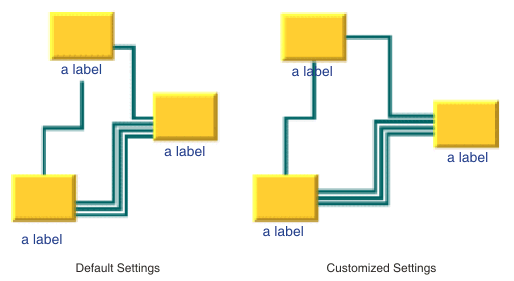
In the following figure, the yellow shading indicates the subgraph to which the nonrecursive link layout is currently applied. The top-level graph is on the left and on the right is the subgraph, which is shaded yellow. If the intergraph links mode is enabled, both the red (intergraph) and blue (normal) links are routed. If the intergraph links mode is disabled, only the blue (normal) links are routed. The gray links are not routed because they do not belong to the graph to which the link layout is applied.
Links routed in a nested graph: top-level graph and then subgraph
To route
all links of a nested graph, you need to apply the Link Layout recursively. Details of the recursive layout mechanism are explained in
Recursive layout. For example:
layout.setInterGraphLinksMode(true);
layout.performLayout(force, redraw, true);
routes the intergraph links recursively in all subgraphs. If you use a layout provider (a class that implements the interface IlvLayoutProvider ), you need to set the intergraph links mode for all subgraphs explicitly:
IlvLayoutProvider layoutProvider = ...
// first, set the intergraph mode for all layouts
Enumeration e = graphModel.getLayouts(layoutProvider, true);
while (e.hasMoreElements()) {
IlvGraphLayout layout = (IlvGraphLayout) e.nextElement();
if (layout instanceof IlvLinkLayout)
((IlvLinkLayout) layout).setInterGraphLinksMode(true);
}
// then perform layout recursively using the provider
graphModel.performLayout(layoutProvider, force, redraw, true);
To perform the intergraph link routing recursively in combination with a layout that places the nodes or that arranges labels, use an instance of the class
IlvMultipleLayout to encapsulate the Link Layout and the other layouts, and then perform the Multiple Layout recursively all at once. For details, see
Recursive layout.
Spacing parameters in short link layout
Since the short link mode places the links freely in the space, only two parameters are necessary to control the spacing: the minimum distance between links and the minimum length of the final segment.
Figure
Spacing parameters for the short link layout shows the spacing parameters used in short link mode.
Spacing parameters for the short link layout
Link offset
The layout algorithm computes the final connecting segments of the links (that is, the segments near the origin and destination nodes) to obtain parallel lines spaced at a user-defined distance. In short link mode, the algorithm takes into account the width of the links when computing the offset.
Example of specifying link offset (Link Layout algorithm)
To specify the offset:
In CSS
Add to the LinkLayout section:
layoutMode : "SHORT_LINKS";
linkOffset : "3.00";
In Java
Use the method:
void setLinkOffset(float offset)
The offset is measured from the border of one link to the nearest border of the other link. Therefore, if the specified offset is zero, the border of a link touches the border of its neighboring link.
Minimum final segment length
You can specify a minimum value for the length of the final connecting segments of the links (that is, the segments near the origin and destination nodes).
Example of specifying minimum final segment length (Link Layout algorithm)
In CSS
Add to the LinkLayout section:
layoutMode : "SHORT_LINKS";
minFinalSegmentLength : "15.0";
In Java
Use the method:
void setMinFinalSegmentLength(float length)
Connector style
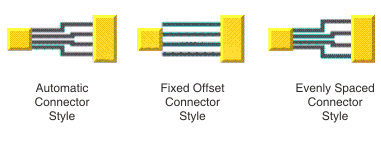
The layout algorithm positions the end points of links (the connector pins) at the nodes automatically. The connector style parameter specifies how these end points are calculated.
Connector styles
The layout algorithm provides two connector styles. You can set the connector style globally, in which case all the nodes (hence, all the links) have the same connector style, or locally on each node (that is, for all the links connected to the node), in which case different connector styles occur in the same drawing.
Global connector style
Example of specifying the global connector style (Link Layout algorithm)
To specify the global connector style:
In CSS
Add to the LinkLayout section:
globalConnectorStyle: "EVENLY_SPACED_PINS";
In Java
Use the following method:
void setGlobalConnectorStyle(int style);
The valid values for style are:
IlvShortLinkLayout.FIXED_OFFSET_PINS IlvShortLinkLayout.EVENLY_SPACED_PINS IlvShortLinkLayout.AUTOMATIC_PINS (the default)
Uses the connector style
FIXED_OFFSET_PINS except if it pushes a connection point outside the border the link is attached to, in which case it uses the connector style
EVENLY_SPACED_PINS. See
Spacing parameters for the short link layout as an example.
IlvShortLinkLayout.MIXED_STYLE Each node can have a different connector style. The style of each individual node can be set to have different connector styles occurring in the same graph.
In CSS, you omit the prefix IlvShortLinkLayout when specifying the value of the connector style.
Individual connector style
All nodes have the same connector style unless the global connector style is IlvShortLinkLayout.MIXED_STYLE.
Only when the global connector style is set to MIXED_STYLE can each node have an individual connector style.
Example of specifying individual node connector style (Link Layout algorithm)
To specify the connector style of an individual node:
In CSS
Specify a rule that selects the node, for instance:
LinkLayout {
globalConnectorStyle : "MIXED_STYLE";
}
#node1
{
ConnectorStyle : "EVENLY_SPACED_PINS";
}
In Java
Use the following methods:
void setConnectorStyle(Object node, int style);
int getConnectorStyle(Object node);
The valid values for style are:
IlvShortLinkLayout.FIXED_OFFSET_PINS IlvShortLinkLayout.EVENLY_SPACED_PINS IlvShortLinkLayout.AUTOMATIC_PINS (the default).
The default value is 10.
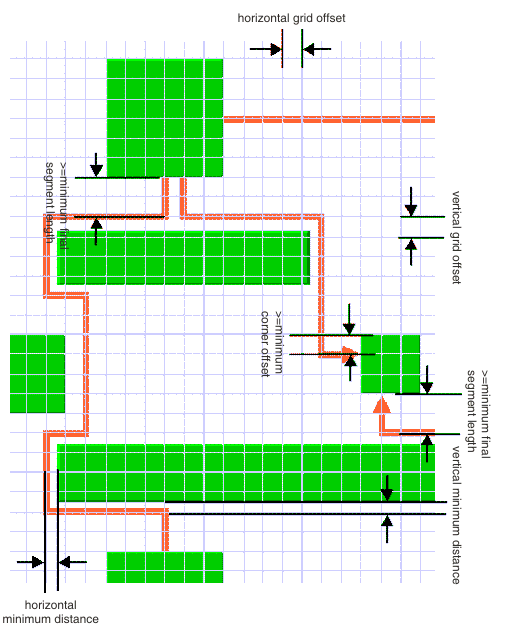
Spacing parameters in long link layout
The long link mode places the links on a grid. Four parameters control the grid offsets and five parameters control the spacing of links in relation to other objects. Figure
Spacing parameters for long link layout shows the spacing parameters used in the long link mode.
Spacing parameters for long link layout
Grid offset parameters
The grid offset parameters control the spacing between grid lines. Links are routed such that the center of the orthogonal link segments is on the grid lines. The grid offsets must be set to a value larger than the largest link width value to avoid links that visually overlap.
Example of specifying grid offset parameters (Link Layout algorithm)
To set the horizontal and vertical grid offset:
In CSS
Add these statements to the LinkLayout section:
horizontalGridOffset : "5.0";
verticalGridOffset : "5.0";
In Java
Use the methods:
void setHorizontalGridOffset(float offset);
void setVerticalGridOffset(float offset);
The grid offset is the critical parameter for the long link mode. If the grid offset is too large, there might be no grid lines between nodes even though some free space exists between the nodes. In this case, the link routings cannot use the free space. However, if the grid offset is too small, the algorithm needs a long time to traverse the grid.
Grid base parameters
Sometimes it is necessary to shift the whole grid by a small amount because the nodes are not aligned on the grid. For example, to have grid lines at positions 3, 13, 23, 33, and so on, you can set the grid offset to 10 and the grid base to 3.
Example of specifying grid base parameters (Link Layout algorithm)
To adjust the grid base:
In CSS
Add these statements to the LinkLayout section:
horizontalGridBase : "3.0";
verticalGridBase : "3.0";
In Java
Use the methods:
void setHorizontalGridBase(float coordinate);
void setVerticalGridBase(float coordinate);
Minimum distance parameters
The minimum distance controls how closely a link can be placed to the border of a node that needs to be bypassed. If the node border is not aligned to the grid, the minimum distance specifies the next grid line close to the border that can be used. For instance, if a node covers the x-coordinates 25 - 65 on a grid with offset 10 and base 0, the next grid lines used to bypass the node would normally be at 20 and 70. If you specify a minimum distance of 8, these grid lines are too close to the node and then the grid lines at 10 and 80 would be used.
Example of specifying minimum distance parameters (Link Layout algorithm)
To set the minimum distance:
In CSS
Add these statements to the LinkLayout section:
horizontalMinOffset : "10.25";
verticalMinOffset : "10.25";
In Java
Use the methods:
void setHorizontalMinOffset(float offset);
void setVerticalMinOffset(float offset);
Minimum node corner offset parameter
The minimum corner offset is the minimum distance between a node corner and a link that connects to the node. This parameter is used to avoid having a link that connects exactly to the corner or outside the border of the node (see
Minimum corner offset).
Example of specifying minimum node corner offset parameter (Link Layout algorithm)
To set the minimum corner offset:
In CSS
Add to the LinkLayout section:
minNodeCornerOffset : "5.2";
In Java
Use the method:
void setMinNodeCornerOffset(float offset);
Minimum corner offset
Minimum final segment length
As with the short link mode, the long link mode respects the minimum value for the length of the final connecting segments of the links.
Example of specifying minimum final segment length (Link Layout algorithm)
To set the minimum length of the final segment:
In CSS
Add to the LinkLayout section:
minFinalSegmentLength : "15.0";
In Java
Use the method:
void setMinFinalSegmentLength(float length)
For experts: additional features of Link Layout
Using a node-side filter
Some applications require that links are not connected to specific sides of certain nodes. With the Link Layout algorithm, you can restrict to which node side a link can connect by using a node-side filter.
A node-side filter is any class that implements the interface
IlvNodeSideFilter. This interface defines the following method:.
public boolean accept(IlvGraphModel graphModel,
Object link,
boolean origin,
Object node,
int side);
This method lets the input link connect its origin or destination to the input side of the input node.
As an example, assume that the application requires that for end nodes of type
IlvShadowRectangle, links can connect their origin only at the top and bottom side.
For end nodes of type
IlvReliefRectangle, links can connect their destination only at the left and right side. You can obtain this result with the following node-side filter:
class MyFilter implements IlvNodeSideFilter
{
public boolean accept(IlvGraphModel graphModel,
Object link,
boolean origin,
Object node,
int side)
{
if (node instanceof IlvShadowRectangle && origin)
return(side == IlvDirection.Top || side == IlvDirection.Bottom);
if (node instanceof IlvReliefRectangle && !origin)
return(side == IlvDirection.Left || side == IlvDirection.Right);
return true;
}
}
Example of setting node-side filter (Link Layout algorithm)
To set this node-side filter:
In CSS
SDM allows you to specify the node-side constraints using the
NodeSideForOrigin and
NodeSideForDestination properties. For more information, see
Per-object properties of the LinkLayout renderer in
Developing with the JViews Diagrammer SDK.
In Java
Call:
layout.setNodeSideFilter(new MyFilter());
To remove the node-side filter, call:
layout.setNodeSideFilter(null);
Using a node box interface
Some applications require that the effective area of a node is not exactly its bounding box. For example, if the node has a shadow, the shadow is included in the bounding box. The shadow might not be considered as an obstacle for the links. In this case, the effective bounding box of a node is smaller than the bounding box returned by IlvGraphic.boundingBox.
Example of using a node box interface (Link Layout algorithm)
In CSS
It is not possible to set the node box interface.
In Java
You can modify the effective bounding box of a node by implementing a class that implements the
IlvNodeBoxInterface.
This interface defines the following method:
public IlvRect getBox(IlvGraphModel graphModel, Object node);
By using this method, you can obtain the effective bounding box. For example, to set a node box interface that returns a smaller bounding box for all nodes of type
IlvShadowRectangle, call:
layout.setNodeBoxInterface(new IlvNodeBoxInterface() {
public IlvRect getBox(IlvGraphModel graphModel, Object node) {
IlvRect rect = graphModel.boundingBox(node);
if (node instanceof IlvShadowRectangle) {
// need a rect that is 4 units smaller
rect.resize(rect.width-4.f, rect.height-4.f);
}
return rect;
}
});
Using a link connection box interface
By default, the connection points of the links are distributed on the border of the bounding box of the nodes. Sometimes, it can be necessary to place the connection points on a rectangle that is smaller or larger than the bounding box. For instance, it can happen when labels are displayed below or above nodes.
Using a link connection box interface to modify the position of connection points (Link Layout algorithm)
In CSS
It is not possible to set the link connection box interface.
In Java
You can modify the position of the connection points of the links by implementing a class that implements the
IlvLinkConnectionBoxInterface. It is a subinterface of
IlvNodeBoxInterface (see
Using a node box interface). It defines again the method:
public IlvRect getBox(IlvGraphModel graphModel, Object node);
This method allows you to return the effective rectangle on which the connection points of the links are placed.
Additionally, the interface
IlvLinkConnectionBoxInterface defines a second method:
public float getTangentialOffset(IlvGraphModel graphModel, Object node, int
nodeSide);
This method is used only in the short link mode. For details, see
Using a link connection box interface. In Link Layout in long link mode, implement the method by returning the value 0.
For experts: special options of short link layout
The Link Layout algorithm uses the class
IlvShortLinkLayout as a subalgorithm.
IlvShortLinkLayout is a subclass of
IlvGraphLayout and can be used a stand-alone as well. To access the instance of
IlvShortLinkLayout that is used by the Link Layout algorithm, call:
IlvShortLinkLayout getShortLinkLayout();
Using this accessor, you can control many special features of the Short Link Layout that are not made available by the IlvLinkLayout class because these features are for experts only.
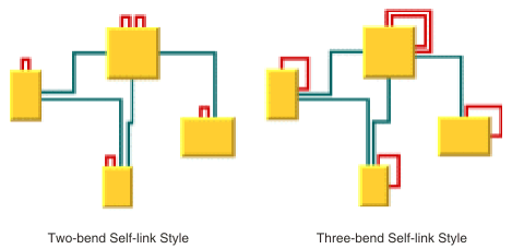
Self-link style
Self-links are links whose origin and destination are the same node. The Short Link Layout provides two optional shapes for self-links.
Self-link style options
Example of setting the style of the self-links (Link Layout algorithm)
To set the style of the self-links:
In CSS
Add to the LinkLayout section:
layoutMode : "SHORT_LINKS";
globalSelfLinkStyle : "TWO_BENDS_ORTHOGONAL_STYLE";
In Java
Call
layout.getShortLinkLayout(). setGlobalSelfLinkStyleThe valid values for style are:
IlvShortLinkLayout.TWO_BENDS_ORTHOGONAL_STYLE IlvShortLinkLayout.THREE_BENDS_ORTHOGONAL_STYLE Number of optimization iterations
The link shape optimization is stopped if the time exceeds the allowed time; see
Allowed time (LL)), or if the number of iterations exceeds the allowed number of iterations.
Example of specifying the number of optimization iterations (Link Layout algorithm)
To set the allowed number of iterations to 3:
In CSS
Add to the LinkLayout section:
layoutMode : "SHORT_LINKS";
allowedNumberOfIterations : "3";
In Java
Call:
layout.getShortLinkLayout().setAllowedNumberOfIterations(3);
NOTE You might want to disable the link shape optimization by setting the number of iterations to zero to increase the speed of the layout process.
Evenly spaced pins margin ratio
The margin ratio allows you to customize the way connection points are computed when the connector style (see
Connector style) is
EVENLY_SPACED_PINS, and when the
AUTOMATIC_STYLE places the connection points using the
EVENLY_SPACED_PINS style. This option has no effect if the connector style
FIXED_OFFSET_PINS is used.
In the ““evenly spaced pins”” connector style, the connection points of the links are evenly spaced along the node border, preserving a margin to each extremity of the node border. The size of this margin is controlled by the margin ratio and is computed by multiplying the offset between the links by the ratio.
Example of specifying the margin ratio (Link Layout algorithm)
To specify this option:
In CSS
Add to the LinkLayout section:
layoutMode: "SHORT_LINKS";
evenlySpacedMarginRatio: "0.2";
In Java
Call
layout.getShortLinkLayout(). setEvenlySpacedPinsMarginRatioThe input value must be a positive or zero value. The default value is
0.5.
Evenly Spaced Pins Margin Ratio shows examples of values with their meaning.
Evenly Spaced Pins Margin Ratio
Ratio value | Meaning |
0 | No margin. |
0.5 (default value) | The margin is equal to half the offset between the links. |
1 | The margin is equal to the offset between the links. |
2 | The margin is equal to twice the offset between the links. |
Link overlap nodes forbidden
With this option you can request the layout algorithm to avoid strictly reshaping links, such that they overlap some nodes. If overlaps are not forbidden, the algorithm tries to avoid overlaps anyway, but can create overlaps, for example, for the link to cross other links.
NOTE Forbidding overlaps can slow down the layout and can increase the number of bends for those links that would overlap nodes if overlaps were not strictly forbidden.
Example of specifying link overlap nodes forbidden (Link Layout algorithm)
To specify this option:
In CSS
Add to the LinkLayout section:
layoutMode: "SHORT_LINKS";
linkOverlapNodesForbidden: "true";
In Java
Call
layout.getShortLinkLayout(). setLinkOverlapNodesForbidden The default value of this option is false.
When overlaps are forbidden, the Short Link Layout algorithm uses the Long Link Layout as an auxiliary algorithm for laying out only the links that would otherwise overlap nodes.
Example of specifying Long Link Layout when overlaps forbidden (Link Layout algorithm)
To retrieve the auxiliary instance of Long Link Layout:
In CSS
It is not possible to access the auxiliary Long Link Layout, nor to tailor this auxiliary Long Link Layout.
In Java
Call this method on the IlvShortLinkLayout instance:
IlvLongLinkLayout getAuxiliaryLongLinkLayout()
This method allows you to get this auxiliary layout instance and to customize its parameters if needed. Notice that you must not modify the origin and destination point mode, nor disable the preservation of fixed links. Notice also that an IlvGraphModel instance is attached to the IlvLongLinkLayout instance only if needed, therefore the method getAuxiliaryLongLinkLayout().getGraphModel() can return null.
Incremental link reshape mode
In incremental mode, it is possible to customize the rules used by Short Link Layout to determine which links must keep their current shape as much as possible, as computed by the previous layout execution. With incremental link reshape mode, you can customize these rules separately for two categories of links.
See the methods:
IlvShortLinkLayout.getLinkConnectionBoxInterface()
and
IlvShortLinkLayout.getNodeBoxInterface()
The ““modified links””: links that have either a different ““link connection box”” or are connected to nodes that have a different bounding box as during the previous layout execution.
The ““unmodified links””: links that have the same ““link connection box”” and are connected to nodes that have the same bounding box as during the previous layout execution.
The mode can be customized either for both or for only one of these categories of links.
The incremental link reshape mode has no effect if incremental mode is disabled.
The layout algorithm provides two incremental link reshape modes. You can set the mode globally, in which case all the links have the same mode, or locally on each link, in which case different modes occur in the same drawing.
Global incremental link reshape mode
Example of specifying a global incremental link reshape mode (Link Layout algorithm)
To specify the global incremental link reshape mode:
In CSS
Add, for instance, these statements to the LinkLayout section:
globalIncrementalModifiedLinkReshapeMode: "FIXED_NODE_SIDES_MODE";
globalIncrementalUnmodifiedLinkReshapeMode: "FIXED_SHAPE_TYPE_MODE";
In Java
Use the following methods:
The valid values for mode are:
IlvShortLinkLayout.FIXED_SHAPE_TYPE_MODE (the default)
The incremental layout preserves the shape type of the link. This means that both the number of bends and the node sides to which the link is connected are preserved.
IlvShortLinkLayout.FIXED_NODE_SIDES_MODE The incremental layout preserves the node sides to which the links are connected.
IlvShortLinkLayout.FIXED_CONNECTION_POINTS_MODE The incremental layout preserves the connection points of the links.
IlvShortLinkLayout.FIXED_MODE The links are not reshaped at all during incremental layout. Only newly added links are rerouted.
IlvShortLinkLayout.FREE_MODE The incremental layout is allowed to freely reshape the links. It is equivalent to a non-incremental behavior for all the links, hence it is recommended to disable the incremental mode instead of using FREE_MODE as global incremental reshape mode.
IlvShortLinkLayout.MIXED_MODE Each link can have a different mode.
In CSS, you can omit the prefix IlvShortLinkLayout when specifying the value of the mode.
Individual incremental link reshape mode
All links have the same incremental link reshape mode unless the global incremental link reshape mode is IlvShortLinkLayout.MIXED_MODE.
Only when the global mode is set to MIXED_MODE can each link have an individual mode.
Example of specifying an individual incremental link reshape mode (Link Layout algorithm)
To specify the mode of an individual link:
In CSS
Write a rule that selects the link, for instance:
LinkLayout {
layoutMode: "SHORT_LINKS";
globalIncrementalModifiedLinkReshapeMode: "MIXED_MODE";
globalIncrementalUnmodifiedLinkReshapeMode: "MIXED_MODE";
}
#link1{
IncrementalModifiedLinkReshapeMode: "FIXED_NODE_SIDES_MODE";
IncrementalUnmodifiedLinkReshapeMode: "FIXED_SHAPE_TYPE_MODE";
}
In Java
Use the following methods on the IlvShortLinkLayout instance:
void setIncrementalModifiedLinkReshapeMode(Object link, int mode);
void setIncrementalUnmodifiedLinkReshapeMode(Object link, int mode);
int getIncrementalModifiedLinkReshapeMode(Object link);
int getIncrementalUnmodifiedLinkReshapeMode(Object link);
The valid values for mode are:
IlvShortLinkLayout.FIXED_SHAPE_TYPE_MODE (the default)
IlvShortLinkLayout.FIXED_NODE_SIDES_MODE IlvShortLinkLayout.FIXED_CONNECTION_POINTS_MODE IlvShortLinkLayout.FREE_MODE IlvShortLinkLayout.FIXED_MODE Same shape for multiple links
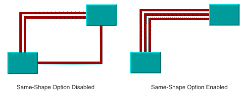
You can force the layout algorithm to compute the same shape for all the links that have common origin and destination nodes. The links have parallel shapes.
When this option is disabled, the layout is free to compute different shapes for links connecting the same pair of nodes. Generally, different shapes are chosen to avoid some overlaps.
Same shape for multiple links option
Example of specifying the same shape for multiple links (Link Layout algorithm)
To enable the same shape for multiple links:
In CSS
Add to the LinkLayout section:
layoutMode: "SHORT_LINKS";
sameShapeForMultipleLinks : "true";
In Java
Use the method:
layout.getShortLinkLayout().setSameShapeForMultipleLinks(true);
The default value is false.
Link crossing penalty
The computation of the shape of the links is driven by the objective to minimize a cost function, which is proportional to the number of link-to-link crossings and link-to-node crossings. By default, these two types of crossing have equal weights of 1. You can increase the weight of the link-to-node crossings.
Example of specifying link-to-node crossing penalty (Link Layout algorithm)
To increase the weight of the link-to-node crossings:
In CSS
Add to the LinkLayout section:
layoutMode: "SHORT_LINKS";
linkToNodeCrossingPenalty : "5.0";
In Java
Use the method:
layout.getShortLinkLayout().setLinkToNodeCrossingPenalty(5.f);
This setting increases the possibility of obtaining a layout with no link-to-node crossings (or with only a few crossings), at the expense of the possibility that more link-to-link crossings could occur.
Alternatively, you can increase the weight of the link-to-link crossings.
Example of specifying link-to-link crossing penalty (Link Layout algorithm)
To increase the weight of the link-to-link crossings, for instance, to a value of 3:
In CSS
Add to the LinkLayout section:
layoutMode: "SHORT_LINKS";
linkToLinkCrossingPenalty : "3.0";
In Java
Use the method:
layout.getShortLinkLayout().setLinkToLinkCrossingPenalty(3.f);
This setting increases the possibility of obtaining a layout with no link-to-link crossings (or with only a few crossings), at the expense of the possibility of more link-to-node crossings.
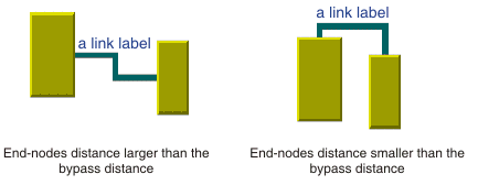
Bypass distance
If the origin and destination nodes are too close, there might not be enough space for routing the link directly between the end nodes. Therefore, by default, if the end nodes are closer than a threshold distance, the layout chooses link shapes that bypass the interval between close nodes. (See
End nodes and bypass distance.)
End nodes and bypass distance
The bypass distance is the minimum distance between the origin and destination nodes for which a link shape going directly from one node to another is allowed. The algorithm tries to avoid link shapes that connect directly the sides of the end nodes that are closer than the bypass value.
Example of specifying the bypass distance (Link Layout algorithm)
To set the bypass distance:
In CSS
Add to the LinkLayout section:
layoutMode: "SHORT_LINKS";
bypassDistance : "3.0";
In Java
Call
void setBypassDistance(float dist)
The default value is a strictly negative value. If the bypass distance is strictly negative, the value of the minimum final segment length parameter is used as the bypass distance. See
Minimum final segment length. It allows the automatic adjustment of the bypass distance according to the current value of the minimum final segment length. This behavior is suitable in most cases. You can specify a nonnegative value to override the default behavior.
Using a link connection box interface
By default, the connection points of the links are distributed on the border of the bounding box of the nodes symmetrically with respect to the middle of each side. Sometimes, it might be necessary to place the connection points on a rectangle smaller or larger than the bounding box, possibly in an asymmetric way. For example, when labels are displayed below or above nodes.
Example of using a link connection box interface to modify the position of the connection points (Link Layout algorithm)
You can modify the position of the connection points of the links by implementing a class that implements the
IlvLinkConnectionBoxInterface interface.
In CSS
It is not possible to set the link connection box interface.
In Java
This interface defines the following method:
public IlvRect getBox(IlvGraphModel graphModel, Object node);
This method allows you to return the effective rectangle on which the connection points of the links are placed.
A second method defined on the interface allows the connection points to be “shifted” tangentially, in a different way for each side of each node:
public float getTangentialOffset(IlvGraphModel graphModel, Object node, int
nodeSide);
For instance, to set a link connection box interface that returns a link connection rectangle that is smaller than the bounding box for all nodes of type MyNodeEditPart and shifts up the connection points on the left and right side of all the nodes, call:
layout.setLinkConnectionBoxInterface(new IlvLinkConnectionBoxInterface() {
public IlvRect getBox(IlvGraphModel graphModel, Object node) {
IlvRect rect = graphModel.boundingBox(node);
if (node instanceof MyNodeEditPart) {
// for example, the size of the bounding box is reduced by 4 units
rect.resize(rect.width-4.f, rect.height-4.f);
}
return rect;
}
public float getTangentialOffset(IlvGraphModel graphModel,
Object node, int nodeSide) {
switch (nodeSide) {
case IlvDirection.Left:
case IlvDirection.Right:
return -10; // shift up with 10 for both left and right side
case IlvDirection.Top:
case IlvDirection.Bottom:
default:
return 0; // no shift for top and bottom side
}
}
});
Self-link style options shows the effects of customizing the connection box. On the left is the result using the default settings: the connection points are distributed on the bounding box of the node (which includes the label) and are symmetric with the middle of each node side (including the label). On the right is the result after specifying a link connection box interface. On the lower side of the nodes, the links are now connected to the node (passing over the label), while on the left and right sides of the nodes, the connection points are now symmetric to the middle of the node (without the label).
Customization of the link connection box
For experts: special options of long link layout
The Link Layout algorithm uses the class
IlvLongLinkLayout as subalgorithm.
IlvLongLinkLayout is a subclass of
IlvGraphLayout and can be used a stand-alone as well. To access the instance of
IlvLongLinkLayout that is used by the Link Layout algorithm, use the method:
IlvLongLinkLayout getLongLinkLayout();
Using this accessor, you can control many special features of the Long Link Layout that are not made available by the IlvLinkLayout class because these features are for experts only.
Specifying additional obstacles
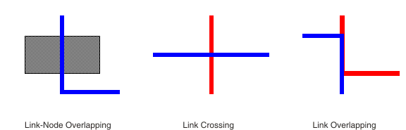
The Long Link Layout algorithm considers nodes to be obstacles that cannot be overlapped and links to be obstacles that can be crossed at an angle of 90 degree (approximately, if the link style is direct), but that cannot be overlapped.
Crossing and overlapping
Example of specifying additional obstacles (Link Layout algorithm)
If an application requires additional obstacles that are not links or nodes, they can be specified as follows:
In CSS
It is not possible to specify additional obstacles in CSS.
In Java
Call:
layout.getLongLinkLayout(). addRectObstacle layout.getLongLinkLayout(). addLineObstacle layout.getLongLinkLayout(). addLineObstacle Rectangular obstacles behave like nodes: links cannot overlap the rectangles. Line obstacles behave like link segments: other links can cross the line segments, but cannot overlap the segments. These obstacle settings can be removed as follows:
In Java
layout.getLongLinkLayout(). removeAllRectObstacles layout.getLongLinkLayout().
Penalties for variable end points
If the termination points of the links are not fixed, the algorithm uses a heuristic to calculate the termination points of each link. It examines all free grid points that are close to the border of the start and end node and assigns a penalty to each grid point. If a node-side filter is installed, the penalty depends on whether the node side is allowed or rejected.
A more precise way to affect how the termination points are chosen is the termination point filter. It allows the user to specify the penalty for each grid point.
Example of specifying the termination point filter (Link Layout algorithm)
In CSS
It is not possible to specify the termination point filter in CSS.
In Java
A termination point filter is a class that implements the interface
IlvTerminationPointFilter that defines the following method:
public int getPenalty(IlvGraphModel graphModel, Object link,
boolean origin, Object node, IlvPoint point,
int side, int proposedPenalty);
To select the origin or destination point of the input link, the input point (a grid point on the input side of the node ) is examined. The proposedPenalty is calculated by the default heuristic of the algorithm. You can return a changed penalty or you can return java.lang.Integer.MAX_VALUE to reject the grid point. If the grid point is rejected, it is not chosen as termination point of the link.
The termination point filter can be set as follows:
Call on the
IlvLongLinkLayout instance:
setTerminationPointFilterManipulating the routing phases
As mentioned in
Long Link Layout algorithm, the algorithm first treats each link individually and then applies a crossing reduction phase to all links. To find a route for an individual link, the algorithm first checks whether a routing (such as a straight line or with only one bend) is possible. If this type of routing is not possible, it uses a sophisticated, but more time consuming, grid search algorithm with backtracking to find a route with many bends.
Example of manipulating the routing phases (Link Layout algorithm)
To disable the phase that finds a
straight-line or one-bend routing:
In CSS
Add to the LinkLayout section:
layoutMode: "LONG_LINKS";
straightRouteEnabled: "false";
In Java
Call:
layout.getLongLinkLayout(). setStraightRouteEnabled The backtrack search for a route with many bends can be done in several ways.
A convenient way is to specify the maximum time available to search for the route for each link.
Example of specifying backtrack steps (Link Layout algorithm)
You can specify the maximum number of backtrack steps.
In CSS
Add to the LinkLayout section:
layoutMode: "LONG_LINKS";
maxBackTrack: "1000";
In Java
Call:
layout.getLongLinkLayout(). setMaxBacktrack The default maximum backtrack number is 30000.
Example of specifying maximum time for route search (Link Layout algorithm)
To specify the maximum time available to search for the route for each link.
In CSS
layoutMode: "LONG_LINKS";
allowedTimePerLink: "4000";
In Java
Call:
The default allowed time per link is 2000 milliseconds (2 seconds).
Finally, you can specify how many steps must be done during the crossing reduction phase.
Example of specifying the number of steps in crossing reduction phase (Link Layout algorithm)
To specify how many steps must be done during the crossing reduction phase:
In CSS
Add to the LinkLayout section
layoutMode: "LONG_LINKS";
numberCrossingReductionIterations: "5";
In Java
Call
Example of disabling crossing reduction (Link Layout algorithm)
You can disable the crossing reduction completely.
In CSS
Add to the LinkLayout section:
layoutMode: "LONG_LINKS";
crossingReductionEnabled: "false";
In Java
Call
Fallback mechanism
If one of the end nodes is inside an enclave, the Long Link Layout algorithm might not be able to find a routing for a link. In
A node inside an enclave, the pink node is inside an enclave. In this case, the backtrack search algorithm fails to find a routing without overlapping nodes. The backtrack search algorithm can also fail if the situation is so complex that the search exceeds the allowed time per link.
A node inside an enclave
When the backtrack search algorithm fails to find a routing, a simple fallback mechanism is applied that creates a routing with a node overlap.
Example of disabling the fallback mechanism (Link Layout algorithm)
To disable the fallback mechanism:
In CSS
Add to the LinkLayout section:
layoutMode: "LONG_LINKS";
fallbackRouteEnabled: "false";
In Java
layout.getLongLinkLayout().setFallbackRouteEnabled(false);
If the fallback mechanism is disabled, these links are not routed at all and remain in the same shape as before the layout. In Java code, you can retrieve the links that could not be routed in the usual way without the fallback mechanism.
Example of retrieving links without the fallback mechanism (Link Layout algorithm)
To retrieve the links that could not be routed in the usual way without the fallback mechanism:
In Java
Enumeration e = layout.getLongLinkLayout().getCalcFallbackLinks();
For example, you can iterate over these links and apply your own specific fallback mechanism instead of the default fallback mechanism of the Long Link Layout algorithm.
Copyright © 2018, Rogue Wave Software, Inc. All Rights Reserved.