Using composite graphics
Shows how to use composite graphics in your diagrams.

Provides a short overview of the Composite Graphics capability in Rogue Wave® JViews Diagrammer and describes the Composite Graphics classes.
Shows how to build a composite node in the style sheet.
Shows how to build a composite node using Java™.
What is a composite graphic object?
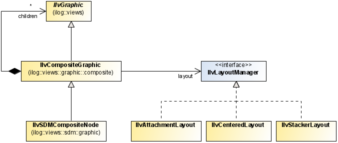
The Composite Graphics capability consists of a set of classes that help you to combine simple graphic objects to build more complex graphic objects according to one of several possible layouts. You can modify a composite graphic object dynamically to add or remove child elements. This facility supports nested composite graphics in which a child element is itself a composite graphic object.
In Rogue Wave® JViews Diagrammer, a Composite Graphic object is an instance of
IlvSDMCompositeNode. This class is in the SDM package but it is a subclass of
IlvCompositeGraphic which is a JViews Framework class, see the following class diagram.
Composite graphics classes available in Rogue Wave JViews Diagrammer
A composite graphic is made up of child graphics, which are positioned according to a composite layout by a Layout Manager,
IlvLayoutManager.
Each child can be an
IlvGraphic object or itself an
IlvCompositeGraphic object.
There are three possible Layout classes:
IlvSDMCompositeNode can have child graphics in different layers; this feature allows you to keep one child always on top.
In Rogue Wave JViews Diagrammer, you can create composite graphic objects through the style sheet, because the
CSS for Java syntax has been extended to handle composite graphics concepts.
Building composite nodes in CSS
This section explains how to style nodes as composite graphics by building a composite graphic directly in the
style sheet.
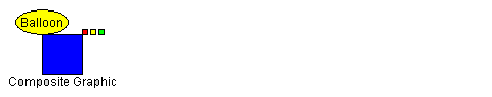
If you follow the steps given in this section, you will obtain the composite graphic shown in the following figure.
The example composite graphic
Note that this composite graphic itself contains composite graphics.
This composite graphic will be used to represent nodes of a specific
user-defined type.
The data to be displayed comes from the XML file shown in the following code example.
The example XML data file
<?xml version="1.0" encoding="UTF-8"?>
<SDM>
<MyNode >
<property name="x">100</property>
<property name="y">100</property>
<property name="label">Composite Graphic</property>
<property name="alarm">Balloon</property>
</MyNode>
</SDM>
There is just one
node defined, with user-defined type
MyNode.
The x and y properties give the location of the node.
Each of the other properties will be styled as a child of a composite graphic.
To build composite nodes in CSS:
1. Enable Composite Graphics
To make use of composite graphics in the style sheet, enable the Composite Graphics capability in the SDM rule, as follows:
Example 4 –
SDM {
Composite:true;
}
2. Customize some objects as composite graphics
Add rules to customize objects with the user-defined type MyNode as composite graphics, as follows:
Example 5 –
node.MyNode {
class:'ilog.views.sdm.graphic.IlvSDMCompositeNode';
children[0]:@+Rectangle;
}
Subobject#Rectangle {
class:'ilog.views.graphic.IlvRectangle';
width:40;
height:40;
fillOn:true;
background:blue;
}
A composite graphic in Rogue Wave® JViews Diagrammer is an instance of the class
IlvSDMCompositeNode. It always has at least one child element. This first child has index 0 in the
children array. In this example, the first child is created as an
IlvRectangle object. It is defined with the ID
Rectangle in a separate rule.
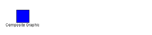
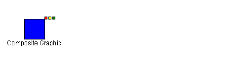
At this stage, the MyNode node would be displayed by the SDM engine as shown in the following figure.
3. 
A composite node with only the first child element
4. Add a decorated child
To display the label attribute of the MyNode object, add another child element to the MyNode rule as shown in the following code example.
Example 6 –
node.MyNode {
class:'ilog.views.sdm.graphic.IlvSDMCompositeNode';
layout:@+AttachmentLayout;
children[0]:@+Rectangle;
children[1]:@+Label;
constraints[1]:@=attachmentLabel;
}
...
Subobject#AttachmentLayout {
class:'ilog.views.graphic.composite.layout.IlvAttachmentLayout';
}
Subobject#Label {
class:'ilog.views.graphic.IlvText';
label:@label;
}
Subobject#attachmentLabel {
class:'ilog.views.graphic.composite.layout.IlvAttachmentConstraint';
hotSpot:TopCenter;
anchor:BottomCenter;
}
This second child has index 1 in the
children array. In this example, the second child is created as an
IlvText object. It is defined with the ID
Label in a separate rule.
Once there is a further child, you need to specify which layout to use. In this case, the Attachment Layout is appropriate because it is the most general. You also need to add a constraint to specify how the second child is attached to the first. The index of the constraints array must correspond to the index of the children array.
For an Attachment Constraint, you must specify the following properties in a separate rule:
hotSpot, which is the point on the subsequent child object by which it is attached
anchor, which is the point on the first child to which the subsequent child is attached
Note that an Attachment can be shared and so the CSS construct @= is used in the MyNode rule. Child graphics cannot be shared and so they are created with the CSS construct @+.
Warning You must NOT use the @# construct to define composite graphics. Only the @+ and @= constructs are allowed. Using @# may lead to a wrong or inconsistent layout.
5. 
A composite node with two child elements
The top center of the second child (
IlvText object) is anchored to the bottom center of the first child (
IlvRectangle object).
The Attachment Layout provides nine possible attachment locations, as shown in the following figure.
6. 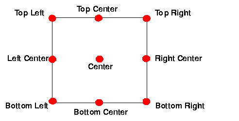
Possible attachment locations
7. Add an Aligned Nested Composite Graphic
To add the three little rectangles at the upper right corner of the blue rectangle, you need to add a child which is itself a composite graphic.
First define the three rectangles with IDs Rect1, Rect2, and Rect3, as shown in the following code example. These are the simple graphic objects which make up the nested composite graphic.
Example 7 –
Subobject#Rect1 {
class:'ilog.views.graphic.IlvRectangle';
width:5;
height:5;
background:red;
fillOn:true;
}
Subobject#Rect2 {
class:'ilog.views.graphic.IlvRectangle';
width:5;
height:5;
background:yellow;
fillOn:true;
}
Subobject#Rect3 {
class:'ilog.views.graphic.IlvRectangle';
width:5;
height:5;
background:green;
fillOn:true;
}
Next add another child element to the MyNode rule as shown in the following code example.
Example 8 –
node.MyNode {
...
children[2]:@+Rectangles;
...
constraints[2]:@=attachmentRectangles;
}
...
Subobject#Rectangles {
class:'ilog.views.sdm.graphic.IlvSDMCompositeNode';
layout:@+StackerLayout;
children[0]:@+Rect1;
children[1]:@+Rect2;
children[2]:@+Rect3;
}
Subobject#attachmentRectangles {
class : "ilog.views.graphic.composite.layout.IlvAttachmentConstraint";
hotSpot:BottomLeft;
anchor:TopRight;
}
Subobject#StackerLayout {
class:'ilog.views.graphic.composite.layout.IlvStackerLayout';
}
This third child has index 2 in the
children array. It is composite graphic, that is, an
IlvSDMCompositeNode. object and it is defined with the ID
Rectangles in a separate rule.
In the Subobject#Rectangles rule, you need to specify which layout to use for the three children. In this case, the Stacker Layout is appropriate because a Stacker Layout is used to align graphics, either horizontally or vertically. The graphics to be aligned horizontally in this example are the children of the composite node.
You also need to add a constraint to the MyNode rule to specify how the third child is attached to the first. In this example, the bottom left of the third child ( IlvSDMCompositeNode object) is anchored to the upper right of the first child ( IlvRectangle object).
At this stage, the MyNode node would be displayed by the SDM engine as shown in the following figure.
8. 
A composite node with three child elements, one a composite
9. Add a Centered Nested Composite Graphic
Finally, add an information balloon to display the alarm attribute.
To add the information balloon with its text, you need to add another child which is itself a composite graphic.
First define the ellipse shape and the label with IDs Ellipse, and BalloonLabel, as shown in the following code example. These are the simple graphic objects which make up the nested composite graphic.
Example 9 –
Subobject#Ellipse {
class:'ilog.views.graphic.IlvEllipse';
background:yellow;
fillOn:true;
}
Subobject#BalloonLabel {
class:'ilog.views.graphic.IlvText';
label:@alarm;
}
Next add another child element to the MyNode rule as shown in the following code example.
Example 10 –
node.MyNode {
...
children[3]:@+Balloon;
...
constraints[3]:@=attachmentBalloon;
}
...
Subobject#Balloon {
class:'ilog.views.sdm.graphic.IlvSDMCompositeNode';
layout:@+CenteredLayout;
children[0]:@+Ellipse;
children[1]:@+BalloonLabel;
}
Subobject#CenteredLayout {
class:'ilog.views.graphic.composite.layout.IlvCenteredLayout';
insets:5,5,5,5;
}
Subobject#attachmentBalloon {
class:'ilog.views.graphic.composite.layout.IlvAttachmentConstraint';
hotSpot:BottomCenter;
anchor:TopLeft;
}
This fourth child has index 3 in the
children array. It is a composite graphic, that is, an
IlvSDMCompositeNode. object and it is defined with the ID
Balloon in a separate rule.
In the Subobject#Balloon rule, you need to specify which layout to use for the two children. In this case, the Centered Layout is appropriate because a Centered Layout is used to center one graphic on another. A Centered Layout displays an outer graphic (the child at index 0) around an inner graphic (the child at index 1). The four insets specify the pixel distances from each edge of the bounding box of the outer graphic. Note that the two child objects maintain their relative position when the composite graphic is resized.
You also need to add a constraint to the MyNode rule to specify how the fourth child is attached to the first. In this example, the bottom center of the fourth child ( IlvSDMCompositeNode object) is anchored to the upper left of the first child ( IlvRectangle object).
Building composite graphics in Java
You can also build composite graphics in Java™ code using the JViews Framework classes in the
ilog.views.graphic.composite package.
To see the same example as the one in
Building composite nodes in CSS but built with the JViews Framework classes instead, see
Composite Graphics in
The Essential JViews Framework.
Copyright © 2018, Rogue Wave Software, Inc. All Rights Reserved.