Building and displaying a 3D View of a map
Describes the class relationship for a 3D View and how to create, customize, and display a 3D View of the terrain.

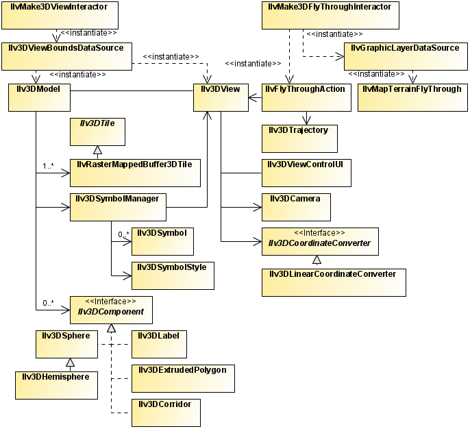
Presents the class relationship for a 3D View.
Explains how to build a 3D terrain.
Explains how to create a 3D view, set camera positions and set parameters to alter the appearance and lighting.
Explains how to add symbology and change its style.
Explains how to add one of the five provided ready-to-use 3D components to your 3D scene.
Presents two examples of API subclassing, one to add custom 3D components, and another to add lighting to 3D components.
Overview
The following figure shows the class relationship for a 3D View.
3D View UML diagram
If your map contains elevation data, for example, a
DTED format map or any other raster data source that acts as an elevation provider, you can display a 3D View of it showing the terrain relief. There is a specific demonstration that explains how to perform your own terrain analysis using the 3D function in
<installdir> /jviews-maps-defense/samples/3dview/index.html.
This view can also display symbols belonging to any symbology, see
Adding 3D components and
Using symbols through the API in
Programming with JViews Maps.
Ilv3DSphere,
Ilv3DHemisphere,
Ilv3DCorridor,
Ilv3DLabel, and
Ilv3DExtrudedPolygon are five predefined 3D shapes ready to be added to your 3D model.
Building the 3D terrain
To build a 3D terrain:
1. First, create an instance of
Ilv3DModel that contains the 3D scene displayed in the 3D View:
Ilv3DModel model3D = new Ilv3DModel(view.getManager());
2. Then, build the mesh representing the terrain within the specified region (the longitude and latitude in radians):
model3D.buildTerrain(Math.toRadians(10),Math.toRadians(45),
Math.toRadians(11), Math.toRadians(46));
This call checks for any data source in the map (stored in the
IlvManager passed to the 3D model) that provides elevation data for the specified region in order to create a 3D mesh of the terrain.
3. This mesh is textured using an image generated from the altitude data (using the color model of the corresponding raster data source) by calling:
model3D.setUse2DViewAsTexture(false);
If the parameter is set to true (the default value), all the layers of the 2D View are draped on top of the terrain mesh, depending on the setting of the Visible in 3D View property of the layer style.
4. In the case of true, you may want to force the texture resolution to be greater than the terrain resolution, especially if you want to use satellite photographs that have much higher precision than the underlying terrain elevation data. You can do this as follows:
model3D.setTextureOversampling(2);
The integer passed in
parameter is used as an exponent to increase the texture size. For example, a value of 2 multiplies the texture width by 4 (2exp2 = 4), and the texture height by 4 also. This is known as Texture Oversampling. Note however, that increasing the Texture Oversampling may lead to texture sizes that are not acceptable to your
OpenGL implementation or your graphics card.
5. You can query the maximum supported texture size by calling the static method:
Ilv3DView.getMaximumSupportedTextureSize().
Displaying the 3D scene
To display the 3D scene:
1. Create a 3D View:
Ilv3DView view3D = new Ilv3DView(model3D);
The 3D View displays the terrain using the default parameters, that is with:
a. The camera located above the terrain, looking at its center along the vertical axis.
b. The distance from the center of the terrain equal to the “radius” of the terrain (that is, the maximum of half the terrain width and half the terrain height).
The simple way to change the position of the camera is using the 3D View mouse interactors, see
Creating a 3D View in
Using the Map Builder for
JViews Maps for Defense for details of how to do this.
xref above targets to defbldr_more.fm in usrbldextdef
However, you can set an absolute position for the camera (for example, as done for a Fly Through) using the following code:
Ilv3DCamera camera = view3D.getCamera();
// Position of the camera in longitude, latitude and elevation.
IlvGeographicPoint cameraGeoPosition = new IlvGeographicPoint(posLon,
posLat, posElev);
// Convert position to 3D space.
Ilv3DVertex pos3D =
view3D.get3DCoordinateConverter().convertTo3DVertex(cameraGeoPosition);
// Set position.
camera.setPosition(new Ilv3DDoubleVector(pos3D.getX(),pos3D.getY(),pos3D.getZ()));
// “Target” point of camera in longitude, latitude and elevation.
IlvGeographicPoint cameraGeoTarget = new Ilv3DGeographicPoint(targetLon,
targetLat, targetElev);
// Convert position to 3D space.
pos3D =
view3D.get3DCoordinateConverter().convertTo3DVertex(cameraGeoTarget);
// Set the target point.
camera.lookAt(new Ilv3DDoubleVector(pos3D.getX(),pos3D.getY(),pos3D.getZ()),
view3D.UP_VECTOR);
NOTE The camera position must be set before the target position to ensure the correct result. Setting the camera position after the target position does not modify the direction in which the camera is looking, but the camera may no longer be looking at the target point.
2. Some parameters of the 3D View can be changed to alter the appearance of the terrain. For example, you can:
a. Render the terrain in Wireframe mode (default is false):
view3D.setWireFrameMode(true);
b. Enable or disable Bilinear Filtering for terrain texture (default is true):
view3D.setBilinearFiltering(true);
c. Enable Lighting in the 3D View (default is false):
view3D.setUseLighting(true);
3. You can then change the following lighting parameters:
a. The horizontal direction of the light by specifying the angle in radians (0 means towards the north).
view3D.setLightOrientationAngle(angleInRadians);
b. The vertical direction of the light by specifying the angle is in radians (0 means horizontal and Math.PI means vertical and downward).
view3D.setLightElevationAngle(angleInRadians);
c. The shading algorithm by enabling gouraud shading (default is true):
view3D.setSmoothShading(true);
d. Change the Height Exaggeration factor:
view3D.setHeightExaggeration(2.0);
e. Change the Terrain Precision factor:
view3D.setTerrainPrecisionFactor(8.0f);
For more information about how to set these parameters, see
Creating a 3D View in
Using the Map Builder for
JViews Maps for Defense.
Adding Symbology to the 3D Model
To add symbology to the 3D model so that symbols are displayed in the 3D View:
IlvSDMEngine symbology = new IlvSDMEngine( );
// Create and configure your symbology here//
…
//
// Create a 3D symbol manager.
Ilv3DSymbolManager symbolManager=new Ilv3DSymbolManager(symbology,view3D);
model3D.setSymbolManager(symbolManager);
The
Ilv3DSymbolManager monitors changes in the symbology and reflects these changes in the 3D View, for example, creation or deletion of symbols, changes in their properties, and so on.
NOTE Only node symbols ( IlvSDMNode ) will be created by the Ilv3DSymbolManager instance and each one will have an associated Ilv3DSymbol object. Links will be ignored and cannot be displayed in the 3D View.
symbolManager.setSymbolStyle(new Ilv3DSymbolStyle());
This style holds several properties, all accessible through “getters” and “setters”.
The following table describes the style properties.
Style properties
Property Name | Description |
iconOffsetAbovePoint | The offset distance in meters between the icon representing the symbol and the point representing its actual location on the map. The default is 1000 meters. |
pointColor | The color of the point representing the symbol location on the map. The default is black. |
preciseImage | A Boolean specifying whether a high resolution image should be used to represent the symbol. The default is true. |
showGroundImprintLine | A Boolean specifying whether a dotted line should be drawn between the location point of the symbol and its projected location on the ground (that is, elevation = 0). The default is true. |
groundImprintColor | The color of the ground imprint line. The default is cyan. |
showSymbolIcon | A Boolean specifying whether the icon representing the symbol should be drawn. The default is true. |
showSymbolPoint | A Boolean specifying whether the point representing the location of the symbol on the map should be drawn. The default istrue. |
symbolsOrdered | A Boolean specifying whether symbols should be drawn using z-buffering. If false, symbols overlap any other object of the 3D scene, including terrain, and are drawn in the same order they were added. The default is true, in which case symbols could be hidden by the terrain, for example a mountain. |
Adding 3D components
Explains how to add one of the five provided ready-to-use 3D components to your 3D scene.
Introduces the ready–to–use 3D components.
Explains how to add a 3D sphere or hemisphere to a 3D scenes and change its appearance.
Explains how to add a corridor to a 3D scene and change its appearance.
Explains how to add an 3D label to a 3D scene.
Explains how to add an extruded polygon to a 3D scene and change its color.
Overview
You can add 3D components to your 3D scene. A 3D component is any object implementing the
Ilv3DComponent interface. The interface requires that the object holds its center position in geographic coordinates (that is, longitude, latitude, and elevation), and is able do draw itself in a specified OpenGL context.
NOTE It is assumed that you are familiar with the OpenGL API and Java™
JOGL API.
Adding an Ilv3DSphere or Ilv3DHemisphere
An Ilv3D Sphere or an Ilv3DHemisphere can be used to represent, for example, a radar coverage zone. It is defined by its center (longitude and latitude in radians, elevation in meters) and its radius in meters.
1. You can add a 3D sphere or hemisphere to a 3D scenes:
// Create a hemisphere located at W0˚,N45˚ and 0 meters above ground, with
// a radius of 20000 meters.
Ilv3DHemisphere hemisphere = new Ilv3DHemisphere(0,Math.PI/4,0,20000);
// Add it to the 3D model.
view3D.get3DModel().add3DComponent(hemisphere);
2. You can refine the appearance of the hemisphere by increasing the number of steps, that is, intermediate points in the longitude-latitude plane (about the center), and along the elevation axis. The default value is 20 for both directions.
hemisphere.setLonLatSteps(50);
hemisphere.setElevationSteps(50);
3. You can change the color of the hemisphere by calling:
hemisphere.setColor(new Color(1.0f,0,0,0.5f)); // half transparent red
NOTE Better clarity is achieved using transparent colors.
Adding an Ilv3DCorridor
An
Ilv3DCorridor can be used to represent, for example, a missile trajectory or an air traffic lane. It is defined by a list of points (longitude, latitude in radians, elevation in meters) and a list of radiuses in meters ( radius of the “tube” at each point).
1. The following example shows how to add a corridor to a 3D scene:
// Corridor coordinates (3 arrays of longitudes, latitudes, elevations).
double[] longs = new double[]{Math.toRadians(10.25),Math.toRadians(11)};
double[] lats = new double[]{Math.toRadians(45.25), Math.toRadians(46)};
double[] elevs = new double[]{0,5000};
// Corridor radius.
double[] radiuses = new double[]{2000,6000}; // in meters
// Create 3D corridor.
Ilv3DCorridor corridor = new Ilv3DCorridor(longs,lats,elevs,radiuses);
// Add it to the 3D model.
model3D.add3DComponent(corridor);
2. You can change the color of the corridor as follows:
corridor.setColor(new Color(0,0,1.0f,0.5f)); // half transparent blue
3. You can also refine its appearance by changing the number of steps about and along the axis of the corridor (default values are 20 about the axis and 1 along the axis for each portion of the corridor).
corridor.setStepsAboutAxis(50);
Adding an Ilv3DLabel
An
Ilv3DLabel Ilv3D is a flat, always-facing and nonzoomable text object used, for example, to annotate other 3D features. It is attached to an anchor point specified by its longitude, latitude and altitude.
2. The following example shows how to add an Ilv3DLabel to a 3D scene:
double longitude = Math.toRadians(45);
double latitude = Math.toRadians(45);
// Create font
Font font = new Font("Times New Roman", Font.ITALIC,16);
Ilv3DLabel label = new Ilv3DLabel(longitude,latitude, 1000,"This is a 3D
label",font);
// Set label parameters
label.setTextColor(Color.BLACK);
label.setBackgroundColor(Color.WHITE);
label.setDrawLabelOutline(true);
// To draw an outline using background color.
model3D.add3DComponent(label);
Adding an Ilv3DExtrudedPolygon
An
Ilv3DExtrudedPolygon is a volume object whose base is a freely specified polygon, but which is then extruded along its altitude axis. It is useful for representing many common shapes such as boxes (buildings for example), coverage zones, cubes, and so on. It is defined by an array of coordinates (longitude and latitude in radians), which make up its base, and two altitudes - one for its base and one for its top.
1. The following example shows how to add an extruded polygon to a 3D scene:
// Coordinates defining the base (2 arrays of longitudes, latitudes,
elevations).
double[] longs = new double[]{Math.toRadians(10.25),Math.toRadians(11)};
double[] lats = new double[]{Math.toRadians(45.25), Math.toRadians(46)};
// Base and top altitudes.
double baseElevation = 1000; // in meters
double topElevation = 1200; // in meters
// Create extruded polygon.
Ilv3DExtrudedPolygon extrudedPoly = new Ilv3DExtrudedPolygon
(longs,lats,baseElevation,topElevation);
// Add it to the 3D model.
model3D.add3DComponent(corridor);
2. You can change the color of the extruded polygon as follows:
extrudedPoly.setColor(new Color(0,0,1.0f,0.5f)); // half transparent blue
Extending the API
Presents two examples of API subclassing, one to add custom 3D components, and another to add lighting to 3D components.
Describes the steps involved in creating a custom 3D component.
Explains how to customize OpenGL rendering.
Adding new 3D components
To create a custom 3D component, implement the
Ilv3DComponent interface:
1. For example, to add a simple cube component, defined by its center and its half-side length:
public class My3DCube implements Ilv3DComponent {
//…
}
2. Implement the
Ilv3DComponent methods relative to the center of the component’s position. The coordinates of the center are stored with double precision:
private double centerLongitude;
private double centerLatitude;
private double centerElevation;
// Also store cube’s side half length (in meters).
private double sideHalfLength = 5000;
public double getCenterLongitude() {
return centerLongitude;
}
public double getCenterLatitude() {
return centerLatitude;
}
public double getCenterElevation() {
return centerElevation;
}
3. Implement the display method that actually draws the component in an OpenGL context.
.
NOTE It is assumed that you are familiar with OpenGL programming and with the Java™ JOGL (OpenGL binding) library.
This method takes an OpenGL context and an
Ilv3DCoordinateConverter. This converter is used to transform any geographic point (longitude, altitude, elevation) into a 3D point in the 3D scene.
Note that the GL context passed in parameter is already centered on the center of the component. This implies that any coordinate should be relative to the center of the component being drawn.
public void display(GL gl, Ilv3DCoordinateConverter converter) {
// Create a GLUT object.
GLUT glut = new GLUT();
// Compute the side length of the cube in 3D space.
// First, find the coordinates of a point on the surface of the cube.
IlvGeodeticComputation comp = new
IlvGeodeticComputation(IlvEllipsoid.SPHERE);
comp.setPoint1(centerLongitude, centerLatitude);
comp.setDistance(sideHalfLength);
comp.setForwardAzimuth(0);
comp.computeGeodeticForward();
double ptLon = comp.getLongitude2();
double ptLat = comp.getLatitude2();
// Now transform the geographic coordinates into 3D space coordinates.
// Convert the center of the cube.
Ilv3DVertex vertex1 =
converter.convertTo3DVertex(new IlvGeographicPoint(
centerLongitude,centerLatitude,centerElevation));
// Convert the second point of the cube.
Ilv3DVertex vertex2 =
converter.convertTo3DVertex(new IlvGeographicPoint(
ptLon, ptLat,centerElevation));
// The half side length of the cube is the distance between the 2 points
// i.e. the norm of the vector.
Ilv3DDoubleVector v = new
Ilv3DDoubleVector(vertex1.getX(),vertex1.getY(),vertex1.getZ()).minus(new
Ilv3DDoubleVector(vertex2.getX(),vertex2.getY(),vertex2.getZ()));
float halfLength = (float)v.length();
// Set the color on the GL context.
gl.glColor4d(1.0,0,0,1.0); // opaque red
// Draw the cube.
glut.glutSolidCube(halfLength);
}
Customizing OpenGL rendering by adding custom lighting for 3D components
To add custom lighting for 3D components subclass the
Ilv3DView and override the
draw3DComponents method to enable and configure lighting on the OpenGL GL context.
The overridden method is as follows:
protected void draw3DComponents(GL gl) {
// Setup lighting before calling super.
gl.glEnable(GL.GL_LIGHTING); // enable lighting
gl.glEnable(GL.GL_LIGHT0); // enable light 0
gl.glEnable(GL.GL_COLOR_MATERIAL); // enable use of color for material
// Color is used for ambient and diffuse material properties.
gl.glColorMaterial(GL.GL_FRONT_AND_BACK,GL.GL_AMBIENT_AND_DIFFUSE);
// Set material shininess.
gl.glMaterialfv(GL.GL_FRONT_AND_BACK,GL.GL_SHININESS,new float[]{75},0);
// Set material specular color.
gl.glMaterialfv(GL.GL_FRONT_AND_BACK,GL.GL_SPECULAR,new
float[]{1.0f,1.0f,1.0f,1.0f},0);
// Set light direction.
float position[] = {0, 1.0f, 0, 1.0f};
gl.glLightfv(GL.GL_LIGHT0, GL.GL_POSITION, position,0);
// Call super method.
super.draw3DComponents(gl);
// Turn the lighting off.
gl.glDisable(GL.GL_LIGHTING);
}
Refer to the OpenGL reference documentation for more information about lighting.
Copyright © 2018, Rogue Wave Software, Inc. All Rights Reserved.