Managing Terrain Analysis
Describes options available for Terrain Analysis.

Describes the purpose of Terrain Analysis.
Explains how to create a Line of Sight.
Explains how to create a Terrain Cut.
Describes available options for 3D Views.
Describes available options for Fly Through paths.
Explains how to create a gradient computation.
Explains how to create a valley computation.
Explains how to create an area of sight.
Terrain Analysis
Terrain analysis enables you to plan the defense of towns, facilities, or terrain contained in your data sources.
Creating a Line of Sight
To create a Line of Sight you must first import a data source containing elevation data, see
Importing a simple data source for more information.
To create a Line of Sight:
1. Set the map to the position and zoom level you require.
2. Click the
3. 
4. button on the toolbar and then draw a line on the map that represents the origin and end of the Line of Sight you want to analyze.
A Line of Sight pane is displayed below the map in the main window and a Lines of Sight layer is added to the Map Layers pane.
5. To change the length or direction of the Line of Sight, click to select it and drag the point at either end of the line to the new position. The Line of Sight is automatically updated.
6. To delete a Line of Sight you can perform one of the following actions:
a. Select the Line of Sight in the Map Layers pane and press the Delete key on your keyboard.
b. Select the Line of Sight in the Map Layers pane, right-click and select Delete Layer from the pop-up menu.
c. Click the
d. 
e. button in the Line of Sight tab to dismiss the Line of Sight and remove the corresponding layer.
7. Set the properties for the Lines of Sight layer in the Map Style property sheet.
The following figure shows the Map Style property sheet for a Line of Sight.
8. 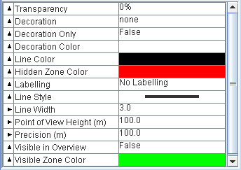
Lines of Sight Layer properties
Creating a Terrain Cut
To create a Terrain Cut you must first import a data source containing elevation data, see
Importing a simple data source for more information.
To create a Terrain Cut:
1. Set the map to the position and zoom level you require.
2. Click the
3. 
4. button on the toolbar and then click the map and draw a line that represents the origin and end of the first part of the polyline you want to draw.
5. Click the mouse button to create a point and start the second part of the polyline, then click again to create a third part and so on. Double-click to end the polyline.
A Line of View pane is displayed below the map in the Map Builder main window and a Terrain Cut layer is added to the Map Layers pane.
6. To reposition the polyline, click to select it and drag the whole line as a unit to the new position. The Line of View is automatically updated.
7. To change the shape of the polyline, click to select it and drag the chosen point to the new position. The Line of View is automatically updated.
8. To add a point to the polyline, place the mouse pointer on the part of the line where you want to add the point, press CTRL and click. A new point is added to the polyline.
9. To remove a point from the polyline, place the mouse pointer on the point you want to remove, press CTRL and click. The point is removed from the polyline.
10. To delete the Terrain Cut layer you can perform one of the following actions:
a. Select the Terrain Cut in the Map Layers pane and press the Delete key on your keyboard.
b. Select the Terrain Cut in the Map Layers pane, right-click and select Delete Layer from the pop-up menu.
c. Click the
d. e. button in the Terrain Cut tab to dismiss the Terrain Cut and remove the corresponding layer.
11. Set the properties for the Terrain Cut layer in the map style property sheet
The following figure shows the Map Style property sheet for a Terrain Cut.
12. 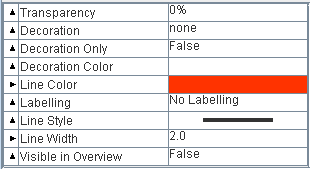
Terrain Cut layer properties
For a detailed description of the properties, see Programming with JViews Maps for Defense
3D Views
Describes available options for 3D Views.
Explains how to create a 3D view.
Explains how to pan a 3D View.
Explains how to zoom in and out of a 3D View.
Explains how to change the 3D View angle and tilt.
Explains how to change terrain style and performance of the 3D View.
Explains how to change the style of symbols.
Explains how to change the 3D bounds.
Explains how to reset the 3D View
Explains how to rotate the 3D View.
Explains how to delete a 3D View.
Explains how to set 3D View properties.
Creating a 3D View
To create a 3D View:
1. Set the map to the position and zoom level you require.
2. Click the
3. 
4. button in the Map Builder main window.
5. Draw a rectangle in the Map View to encompass the area you want to look at. A red rectangle is displayed.
6. A 3D View pane is displayed below the map in the main window and a 3D layer is added to the Terrain Analysis layer in the Map Layers pane.
7. If the 3D view is not visible, select Options>Show Advanced Properties and then select the layer containing the elevation data and set Visible in 3D View to true in the map style property sheet.
NOTE To access the property, you must have the Show Advanced Properties option active (Options>Show Advanced Properties).
Panning a 3D View
The Pan function is automatically activated in the 3D View pane.
To change the position of the 3D View:
Click it and drag it to the new position. In this operation you move both the camera and the point that you are looking at.
To move the 3D View a preset distance:
1. Click the
1. 
1. button or the
1. 
1. button to move the 3D View to the left or right.
2. Click the
3. 
4. button or the
5. 
6. button to move the 3D View up or down.
Zooming in/out of a 3D View
To zoom in and out of a 3D View
Rotate the mouse wheel backwards or forwards to zoom in and out of the 3D View.
or
Use the Zoom In/Out slider.
The following figure shows the Zoom In/Out slider.
Zoom In/Out slider
Changing the 3D View angle and tilt
To change the angle and tilt of the 3D View:
Right-click the image and move the image to the view angle you want. In this operation you change the camera position about the point you are looking at. You can rotate the 3D View through 360 degrees and tilt the image in the same operation.
or
Use the rotate buttons
and
in conjunction with the tilt slider to set the angle and tilt individually.
The following figure shows the Zoom In/Out slider when used with rotate buttons.
Tilt slider
Changing Terrain Style and Performance
To change the terrain style and performance of the 3D View:
Click the
button in the 3D View or right-click in the 3D View and select Change Terrain Style & Performance in the pop-up menu. The 3D View Terrain Style & Performance window appears.
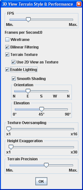
The following figure shows an example of a 3D View Terrain Style & Performance window.
Change Terrain Style and Performance window
To set the number of Frames per Second (FPS):
Drag the slider to the position that corresponds to the FPS you want to set. This sets the number of 3D View refresh operations per second. The lower the value the less the graphics card has to work. If set too high, the graphics card may be overwhelmed and then the CPU will try to help the card, raising the CPU usage to perhaps 100%. If set correctly (depending on the graphics card capabilities), the CPU should remain at around 0% because the graphics card should be able to manage alone. If you want to leave most of the CPU capacity for other tasks, move this slider to the extreme left.
To show the 3D View as a terrain mesh:
Select
Wireframe.
To activate bilinear filtering:
Select
Bilinear Filtering (selected by default). This smooths the texture of the 3D image.
To activate terrain texture options:
1. Select Terrain Texture (selected by default).
2. Select the Use 2D view as texture: the texture applied on top of the 3D terrain mesh is generated by rendering a set of layers belonging to the map. This allows you to display roads on the 3D View. All the layers that have the attribute Visible in 3D View set to true in their map style are drawn as part of the texture.
To activate light computation on a 3D scene:
Select
Enable Lighting.
To use a Gouraud algorithm to compute the shading:
Select
Smooth Shading(otherwise flat shading is applied).
To change the horizontal direction of the light:
Drag the
Orientation slider to the position you want. For example, 'N' means that light is directed towards the north, 'S' towards the south and so on.
To change the vertical direction of the light:
Drag the
Elevation slider to the position you want. You can set the elevation between 0˚ (the light is horizontal) and 90˚ (the light is vertical, descending).
To set Texture Oversampling:
Drag the slider to the position that corresponds to the value you want to set. This value forces the 3D engine to compute higher resolution textures for the terrain. For example, a factor of 4 for leads to generation of a texture 4x4=16 times bigger. Use this slider if you feel that the precision of the default texture does not suit your needs.
To set the Height Exaggeration:
Drag the slider to the position that corresponds to the value you want to set to bring the 3D View into relief. You can set the Height Exaggeration factor to between 1 and 30. By default the exaggeration factor value is 2, which means that all altitudes appear twice as high as they are in reality.
or
Click the 3D View to activate it and press the A key to increase the Height Exaggeration factor of the 3D image or the Z key to decrease it. This brings the 3D View into or out of relief.
To set the Terrain Precision:
Drag the slider to the position that corresponds to the value you want to set. You can choose between 3D View precision and CPU usage by increasing or decreasing this option. When set to minimum, very few 3D points are used to create the terrain mesh, so the terrain is less precise but the display is faster.
When set to maximum, more 3D squares are created, so the terrain is more precise, but the display much slower. In this case, the sooner the zoom level is reached at which each terrain data point has its own mesh rectangle. The more powerful the graphics card, the higher the setting can be.
This is the only option you can use to set the terrain precision. The dynamic more/less detail behavior is hard coded and depends only on the zoom level.
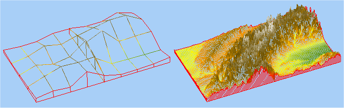
The following figure shows an example of a 3D View (in Wireframe mode), showing a low and high setting for the terrain precision.
Low and high terrain precision settings
Changing the 3D View Symbol Style
To change the style of any symbols you have created in the 3D View:
1. Click the
1. 
1. button in the 3D View or right-click in the 3D View and select Change Symbol Style in the pop-up menu. The 3D View Symbol Style window appears.
The following figure shows the 3D View Symbol Style window.
1. 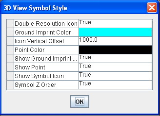
The 3D View Symbol Style window
2. Set the styles you want and click OK.
The following table shows useful properties that you can set.
Style properties
Property | Description |
Double Resolution | Provides high resolution icons in the 3D View. |
Ground Imprint | The color used for the dotted line that shows the ground position of symbols at altitude, such as aeroplanes and missiles. |
Point Color | The color of the point that shows the true position of the symbol. |
Symbol Z Order | Symbols can be displayed with or without respect to the terrain. If set to true, symbols could be hidden by the terrain, for example, behind a mountain. If set to false, symbols are always drawn on top of the terrain |
For a detailed description of the properties, see Programming with JViews Maps for Defense
Changing the 3D Bounds
To change the bounds of the selection rectangle:
In the Map View, select the rectangle and drag a side or corner of it to reset the bounds.
or
Resetting the 3D View
To return the 3D View and the camera to their original state:
Click the
button in the 3D View, or right-click in the 3D View and select Reset Camera from the pop-up menu.
Rotating the 3D View
To rotate the selected terrain in the 3D View:
1. Click the
1. 
1. button to rotate the 3D View clockwise.
2. Click the
3. 
4. button to rotate the 3D View anticlockwise.
Deleting a 3D View
To delete a 3D View you can perform one of the following actions:
Select the 3D View in the Map Layers pane and press the
Delete key on your keyboard.
or
Select the 3D View in the Map Layers pane, right-click and select Delete Layer from the pop-up menu.
or
Click the
button in the 3D View tab to dismiss the 3D View and remove the corresponding layer.
Setting the 3D View properties
To set the properties for the 3D View:
Select the 3D View layer and set properties in the map style property sheet.
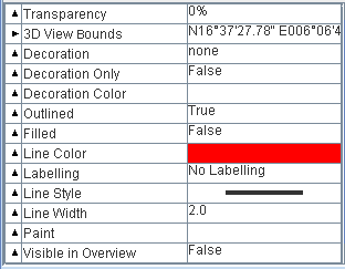
The following figure shows an example of the map style property sheet for a 3D View.
3D View layer properties
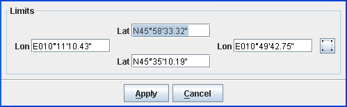
Note that when you set the 3D View Bounds property, the Bounds window is displayed for you to set the coordinates of the bounds.
The following figure shows an example of the Bounds window.
Setting the 3D View bounds property
Fly Through paths
Describes available options for Fly Through paths.
Explains how to create a Fly Through.
Explains how to delete a Fly Through.
Explains how to set Fly Through properties.
Creating a Fly Through
To create a Fly Through you must first import a data source containing elevation data, see
Importing a simple data source for more information.
To create a Fly Through:
1. Set the map to the position and zoom level you require.
2. If you have not already created a 3D View, click the
3. 4. button in the main window. Refer to
Creating a 3D View for details of how to create the 3D View.
5. Click the
6. 
7. button on the toolbar and then click the map and draw a line that represents the origin and end of the first part of the Fly Through trajectory.
8. Click the mouse button to create a point and start the second part of the trajectory, then click again to create a third part and so on. Double-click to end the trajectory.
A Fly Through layer is added to the Map Layers pane. The trajectory represents a route that you can follow visually when the Fly Through is started. The trajectory is displayed in the Fly Through in relief, and a Fly Through button is added to all the currently open 3D View toolbars.
Deleting a Fly Through
Select the Fly Through in the Map Layers pane and press the
Delete key on your keyboard.
or
Select the Fly Through in the Map Layers pane, right-click and select Delete Layer from the pop-up menu.
or
Click the
button in the Fly Through tab to dismiss the Fly Through and remove the corresponding layer.
Setting properties for Fly Through paths
1. Set the properties for the Fly Through layer in the map style property sheet.
The following figure shows an example of a map style property sheet for a Fly Through layer.
1. 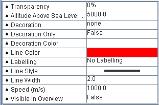
Fly Through layer properties
NOTE The height you set for the Altitude Above Sea Level property remains constant throughout the Fly Through. If the setting is not high enough to clear the mountains, there may be a collision, depending on the trajectory.
2. To start or stop the Fly Through, click the
3. 4. button in the 3D View or right-click and select Start/Stop Fly Through in the pop-up menu.
Creating a gradient computation
To create a gradient computation:
1. Set the map to the position and zoom level you require.
2. Click the
3. 
4. button on the toolbar and then draw a rectangle on the map where you want to compute the gradient.
5. Set the gradient properties in the Gradient Style Settings pane and click OK
The following figure shows an example of the Gradient Style Settings.
6. 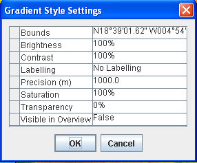
Gradient Style Settings pane
7. The color-coded gradient is displayed in the rectangle you have drawn and a Gradient layer is added to the Map Layers pane. You can change the colors of the Slope data displayed using the Color Model property.
NOTE To access the Color Model property, you must have the Show Advanced Properties option active (Options>Show Advanced Properties).
9. You can also set the properties in the map style property sheet after the layer has been created
Creating a valley computation
To create a valley computation:
1. Set the map to the position and zoom level you require.
2. Click the
3. 
4. button on the toolbar and then draw a rectangle on the map where you want to compute the valleys.
5. Set the valley properties in the Valley Style Settings pane and click OK.
The following figure shows an example of the Valley Style Settings pane.
6. 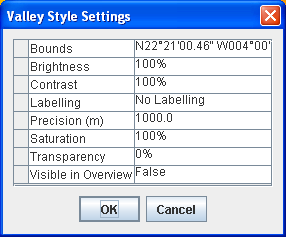
Valley Style Settings pane
7. The color-coded valley/summit information is displayed in the rectangle you have drawn and a Valley layer is added to the Map Layers pane. You can change the colors of the Elevation and Valley data displayed using the Color Model property.
.
NOTE To access the Color Model property, you must have the Show Advanced Properties option active (Options>Show Advanced Properties).
9. You can also set the properties in the map style property sheet after the layer has been created.
For a detailed description of the properties, see Programming with JViews Maps for Defense
Creating an area of sight
To create an area of sight:
1. Set the map to the position and zoom level you require.
2. Click the
3. 
4. button on the toolbar and then move the mouse over the map. A circular image is created around the mouse that gives an approximation of the visible area. The visible area changes according to the terrain as you move the mouse over the map.
5. Click at any point in the map where you want to permanently display the visible and invisible areas. The Area of Sight Style Settings window opens for you to set the styles you want.
The following figure shows an example of the Area of Sight Settings pane.
6. 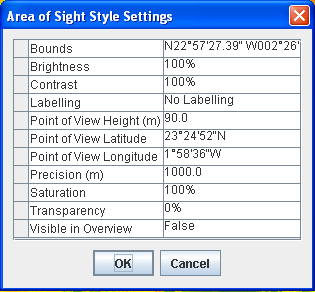
Area of Sight Style Settings window
7. Useful properties that you can set are:
0 | 0 |
Color Model | Color Model: You can use this property to change the color of the visible and invisible terrain. Note: To access the Color Model property, you must have the Show Advanced Properties option active (Options>Show Advanced Properties). |
Point of View Height | You can use this property to change the point of view from ground level to a given altitude (for example, an aeroplane flying at 3000m). |
Precision | You can use this property to increase or decrease the precision of the terrain displayed, but note that the lower the value, the higher the precision but the higher the CPU usage. Set the styles you want and click OK. A detailed Area of Sight is displayed in the Map View. |
8. An Area of Sight layer is added to the Map Layers pane. You can add as many Areas of Sight as you like.
10. You can also set the properties in the map style property sheet after the layer has been created.
Copyright © 2018, Rogue Wave Software, Inc. All Rights Reserved.