3D View interactor
Describes the 3D View interactor.

Explains the use of the
IlvMake3DViewInteractor class to display a 3D View of a selected part of a map.
Provides code for creating the 3D View interactor.
Describes the functioning of the 3D View interactor, the style parameters that can be used and the mouse and GUI interactors available in the 3D View.
Describes the 3D View bean.
Overview
The
IlvMake3DViewInteractor allows the user to select part of the map in a manager view using a selection rectangle, and display a 3D View of it to study the terrain of interest from all angles and all points of view. The 3D View enables you to turn the image through 360 degrees and change the angle of view. You can also use an exaggeration factor to increase or decrease the elevation data display. If specified, the interactor creates a 3D View, which displays a relief of the terrain elevation in a tabbed pane, see
3D View bean.
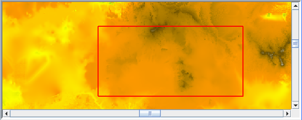
The following figure shows an example of 3D View selection.
3D View selection
The source code for the Map Builder demonstration, which contains all of the code described in this section, can be found at
<installdir> /jviews-maps-defense/samples/3dview/index.htmlCreating and installing the 3D View interactor
To create the 3D View interactor and 3D View, use the following line of code:
IlvMake3DViewInteractor interactor=new IlvMake3DViewInteractor(tabbedpane);
For more information, see
3D View bean.
You can then install this interactor as described in the
Using the GUI beans section in
Programming with JViews Maps.
Using the 3D View interactor
When the interactor is used, it creates an
Ilv3DViewBoundsDataSource and inserts it into the data source model of the manager. This data source manages a single graphic object, an
IlvMapGraphicPath. that represents the bounds of the 3D View.
At the same time, the interactor creates an
IlvMapLayer to display this new graphic object and adds it to the map layer tree under a Terrain Analysis group. The user can use the style of that layer, an
Ilv3DViewBoundsStyle, to customize the graphical attributes of the rectangle and the bounds of that particular 3D View in the map layer tree. This is done by changing the following parameters:
The
Bounds attribute: The coordinates of the area contained within the selection rectangle that determine the size of the 3D View.
The
Line Color attribute: The color defined for the selection rectangle.
Mouse interactors
The following interactors are available on the 3D View using the mouse:
Left click to grab and pan: Moves the 3D View around the panel.
Right-click to grab and rotate: Changes the angle and point of view.
Mouse wheel: Turn the mouse wheel away from you or towards you to zoom in/out.
Graphical User Interface interactors
The following interactors are available in the 3D View using the Graphical User Interface (GUI) buttons, sliders, shortcut menu, and the Terrain Style & Performance window:
Frames per second (FPS): Provides a slider to set the position that corresponds to the FPS you want to set. This sets the number of 3D View refresh operations per second. The lower the value the less the graphics card has to work. If set too high, the graphics card may be overwhelmed and then the CPU will try to help the card, raising the CPU usage to perhaps 100%. If set correctly (depending on the graphics card capabilities), the CPU should remain at around 0% because the graphics card should be able to manage alone. If you want to leave most of the CPU capacity for other tasks, move this slider to the extreme left.
Wireframe: When active, this option shows the 3D View as a terrain mesh.
Bilinear Filtering:When active (selected by default), this option smooths the texture of the 3D image to hide the underlying mesh.
Enable Lighting. When active, this option activates light computation on a 3D scene. You can use this to smooth the shading using a gouraud algorithm to compute it (otherwise flat shading is applied), set the orientation to change the horizontal direction of the light (for example, 'N' means that light is directed towards the north, 'S' towards the south and so on), and set the elevation to change the vertical direction of the light (you can set the elevation between 0˚ (the light is horizontal) and 90˚ (the light is vertical, descending).
Use 2D view as texture: Sets the mode to Use 2D view as texture (selected by default). The 2D View presents a view from a satellite. When this option is inactive, the colors used for the 3D View are generated from the altitude data. When active, all the layers of the 2D View with the map style
Visible in 3D View set are draped on top of the terrain mesh.
Texture Oversampling: Provides a slider to set the position that corresponds to the Texture Oversampling you want to set. You can set the Texture Oversampling value to between 1 and 16. By default Texture Oversampling = 1, which means that there is 1 pixel per 3D square. In this case, the 2D View is displayed using the same resolution as the terrain data.
However, if you have elevation data with a precision of one elevation every 100 meters and you would like to drop a satellite view onto it with a precision of 1 meter, that is, 100 times more precise than the elevation data you have, you can do so using Texture Oversampling.
For example, when set to 2, the 3D square displays 2x2 pixels giving a texture 4 times more precise, and when set to 8 the texture is 8x8=64 times more precise and so on. Note however, that the greater the value, the slower the display, and the greater the memory required.
Height Exaggeration: Provides a slider to set the position that corresponds to the Height Exaggeration factor you want to set. This value determines the degree to which the 3D View is brought into relief. You can set the Height Exaggeration factor to between 1 and 30. By default 1km altitude equals 1km distance.
or
Click the 3D View to activate it and press the A key to increase the Height Exaggeration factor of the 3D image or the Z key to decrease it.
Terrain Precision: Provides a slider to set the position that corresponds to the Terrain Precision you want to set. You can choose between 3D View precision and CPU usage by increasing or decreasing this option. When set to minimum, very few 3D points are used to create the terrain mesh, so the terrain is less precise but the display is faster.
When set to maximum, more 3D squares are created, so the terrain is more precise, but the display much slower. In this case, the sooner the zoom level is reached at which each terrain data point has its own mesh rectangle. The more powerful the graphics card, the higher the setting can be. This is the only option you can use to set the terrain precision. The dynamic more/less detail behavior is hard coded and depends only on the zoom level.
Change Symbol Style: Opens the 3D View Symbol Style window. You can edit the style of any symbols you have created in the 3D View by setting their properties.
Reset Camera: Resets the 3D View and the camera to their original state.
Zoom/Pan/Rotate/Tilt: These operations are carried out by the set of buttons and sliders on the right of the 3D View pane.
In
JViews Maps for Defense, APP-6a symbols (2-dimensional) can be added to a 3D View and managed. For more information, see
Adding Symbology to the 3D Model.
3D View bean
The interactor creates an
Ilv3DView in a tabbed pane as soon as the bounds are drawn on the map, see
Creating and installing the 3D View interactor. This panel displays a 3D View of the selected area of the map.
If the user changes the 3D Views bounds, either by using the select tool, or by modifying the style parameters, JViews Maps for Defense updates the 3D View.
For further information, see
The 3D View bean.
Copyright © 2018, Rogue Wave Software, Inc. All Rights Reserved.