SURFACE Procedure
Draws the surface of a two-dimensional array with hidden lines removed.
Usage
SURFACE, z [, x, y]
Input Parameters
z—A two-dimensional array containing the values that make up the surface. If x and y are supplied, the surface is plotted as a function of the X,Y locations specified by their contents. Otherwise, the surface is generated as a function of the array index of each element of z.
x—(optional) A vector or two-dimensional array specifying the x-coordinates for the surface.
If x is a vector, each element of x specifies the x-coordinate for a column of z. For example, x(0) specifies the x-coordinate for z(0, *).
If x is a two-dimensional array, each element of x specifies the x-coordinate of the corresponding point in z (xij specifies the x-coordinate for zij).
y—(optional) A vector or two-dimensional array specifying the y-coordinates for the surface.
If y is a vector, each element of y specifies the y-coordinate for a row of z. For example, y(0) specifies the y-coordinate for z (*, 0).
If y is a two-dimensional array, each element of y specifies the y-coordinate of the corresponding point in z (yij specifies the y-coordinate for zij).
Keywords
Keywords let you control many aspects of the plot’s appearance. SURFACE keywords are listed below. For a description of each keyword, see Graphics and Plotting Keywords.
Discussion
Note the following restrictions on the use of SURFACE. If the X,Y grid is not regular or nearly regular, errors in hidden line removal will occur.
If T3D is set, the 3D to 2D transformation matrix contained in !P.T must project the Z axis to a line parallel to the device Y axis, or errors will occur.
Example
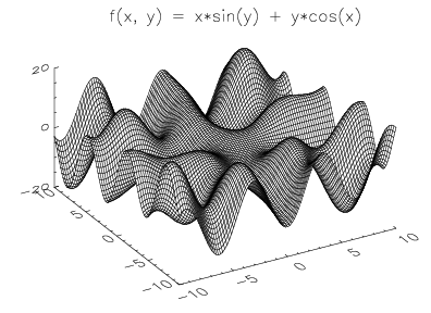
This example displays the surface described by the function:
where:
The results are shown in Surface with Title.
; Create vector of x- and y-coordinates.
x = FINDGEN(101)/5-10
y = x
; Create an array to hold the function values.
z = FLTARR(101, 101)
; Evaluate the function at the given x- and y-coordinates and
; place the result in z.
FOR i=0L, 100 DO FOR j=0L, 100 DO z(i, j) = x(i) * SIN(y(j)) + y(j) * COS(x(i))
; Display surface. The Ax keyword is used to specify angle of
; rotation about the x-axis. The XCharsize, YCharsize, and
; ZCharsize keywords are used to enlarge the characters used
; to annotate the axes.
SURFACE, z, x, y, Ax = 50, XCharsize = 2, YCharsize = 2, $
ZCharsize = 2
; Place a title on the window. Note that the CURSOR procedure
; with Device keyword was used to locate the proper position
; for the title.
XYOUTS, 163, 477, "f(x, y) = x*sin(y) + y*cos(x)", $
Charsize = 2, /Device
|
|
See Also
SHADE_SURF, SHADE_SURF_IRR, SURFACE_FIT, SURFR, T3D, THREED
System Variables: !P.T
For more information, see the PV‑WAVE Programmer’s Guide.


