Parameters
The Bus Layout uses generic parameters, common to other graph layouts, and specific parameters applicable in bus layouts only. Refer to the following sections for general information on parameters among the graph layouts:
The Bus Layout parameters are described in detail in this topic under:
Generic Parameters
The
IlvBusLayout class supports
generic parameters defined in the
IlvGraphLayout class. The following comments describe the particular way in which these parameters are used by this subclass:
Layout Region
The layout algorithm uses the layout region setting (either your own or the default setting) to control the size and the position of the graph drawing. All three ways of specifying the layout region are available for this subclass. (For a description of this parameter in the
IlvGraphLayout class, see
Layout Region.)
Remember that if you are using the default settings, there must be a view (an instance of
IlvView) attached to the grapher. If no view is attached, and no layout region is explicitly specified, the layout algorithm cannot produce reasonable results.
If a layout region is specified, this region is used. If no layout region is specified but a view is attached, the size and position of the graph drawing is computed to approximately fill the view.
The size of the layout is chosen with respect to the layout region (see
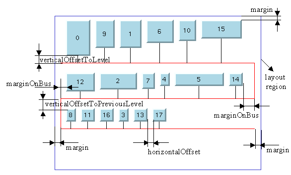
Figure 4.42). The height of the layout region is not taken into account. The height of the layout will be smaller or larger, depending on the number of nodes, the size of the nodes, and the other specified parameters.
Preserve Fixed Links
The layout algorithm does not reshape the links that are specified as fixed. (For more information on link parameters in the
IlvGraphLayout class, see
Preserve Fixed Links.)
Preserve Fixed Nodes
The layout algorithm does not move the nodes that are specified as fixed. (For more information on node parameters in the
IlvGraphLayout class, see
Preserve Fixed Nodes.)
Specific Parameters
The following parameters are specific to the
IlvBusLayout class:
Order
The order parameter specifies how to arrange the nodes.
To specify the ordering option for the nodes, use the method:
The valid values are:
 IlvBusNoOrdering
 The nodes are arranged on the bus in an arbitrary order. This is the default value.
 IlvBusOrderByHeight
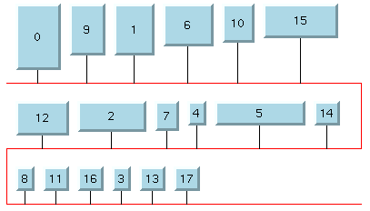
 The nodes are arranged on the bus according to height, starting at the upper-left corner of the bus with the tallest node. This option can save vertical space.
 IlvBusOrderByIndex
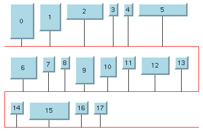
 This option allows you to specify a particular order for the nodes. The nodes are arranged on the bus according to their index values, starting at the upper-left corner of the bus with the node with the smallest index. Nodes for which you do not specify an index are placed after the nodes for which an index is specified.
The IlvBusOrderByIndex option allows you to specify the order of the nodes, according to physical, geographical data for example. If this option is chosen, the algorithm sorts the nodes in ascending order according to their index values.
To obtain the current value, use the method:
The index is an integer value associated with a node and is specified using the method:
The values of the indexes cannot be negative. To obtain the current index of a node, use the method:
If no index is specified for the node, the value NoIndex is returned.
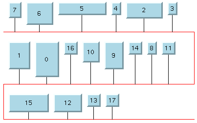
The ordering options for the Bus Layout are illustrated in
Table 4.5.
Ordering Options of the Nodes for the Bus Layout Algorithm
Ordering | Layout |
IlvBusNoOrdering | |
IlvBusOrderByHeight | |
IlvBusOrderByIndex | |
Bus Node
To represent bus topologies, the algorithm reshapes a special node, called the “bus node”, and gives it a “serpent” form. This bus node must be an instance of the
IlvPolyline class. Before performing the layout, you must create this object and add it to the grapher as a node. (The number of points in the object you create is not important.) Then, you must specify the node as “bus node” using the method:
void setBus(IlvPolyline* bus); To obtain the current selection for the bus node, use the method:
You can also use subclasses of
IlvPolyline. (See the code provided in
Code Sample.)
Link Style
When the layout algorithm moves the nodes,
straight-line links, such as instances of
IlvLinkImage, will automatically “follow” the new positions of their end nodes. If the grapher contains other types of links (for example,
IlvPolylineLinkImage or
IlvDoubleSplineLinkImage), the shape of the link may not be appropriate because the intermediate points of the link will not be moved. In this case, you can ask the layout algorithm to automatically remove all the intermediate points of the links (if any). To do this, the following method is provided:
The valid values are:
 IlvLayoutNoReshapeLinkStyle
 None of the links is reshaped in any manner.
 IlvLayoutStraightLineLinkStyle
 All the intermediate points of the links (if any) are removed. This is the default value.
Note: If the IlvLayoutStraightLineLinkStyle style is selected, the layout algorithm calls the method ensureStraightLineLinks on the attached graph model to ensure that all the links have a straight-line shape. With an IlvGrapher, this method may replace links with new types of links. For details on this method, see the Reference Manual. For details on the graph model, see the section Using the Graph Model. |
To obtain the current choice, use the following method:
Dimensional Parameters
Figure 4.42 illustrates the dimensional parameters used in the Bus Layout algorithm. These parameters are:
Figure 4.42 Dimensional Parameters for the Bus Layout Algorithm
Horizontal Offset
This parameter represents the horizontal distance between two nodes. To specify the horizontal offset, use the method:
To obtain the current value, use the method:
Vertical Offset to Level
This parameter represents the vertical distance between a row of nodes and the next horizontal segment of the bus node. To specify this parameter, use the method:
To obtain the current value, use the method:
Vertical Offset to Previous Level
This parameter represents the vertical distance between a row of nodes and the previous horizontal segment of the bus node. To specify this parameter, use the method:
To obtain the current value, use the method:
Margin
This parameter represents the offset distance between the layout region and the bounding rectangle of the layout. To specify this parameter, use the method:
To obtain the current value, use the method:
Margin on Bus
On the odd horizontal levels (first, third, fifth, and so on) of the bus starting from the top, this parameter represents the offset distance between the left side of the first node on the left and the left side of the bus object.
On the even horizontal levels (second, fourth, sixth, and so on) of the bus starting from the top, this parameter represents the offset distance between the right side of the last node on the right and the right side of the bus object. (See
Figure 4.42 for an illustration of the margin-on-bus parameter.)
To specify this parameter, use the method:
To obtain the current value, use the method:
Version 6.0
Copyright © 2015, Rogue Wave Software, Inc. All Rights Reserved.


