Free Layout Mode
The free layout mode arranges the children of each node starting recursively from the root so that the links flow roughly in the same direction. For instance, if the link flow direction is top-down, the root node is placed at the top of the drawing. Siblings (that is, nodes with the same parent) are justified at their top borders, but nodes of different tree branches (that is, nodes with different parents) are not justified.
The following statement sets the free layout mode:
Additional parameter information for free tree layout is as follows:
Flow Direction
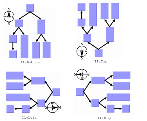
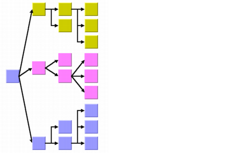
The flow direction parameter specifies the direction of the tree links. The compass icons show the compass directions in these layouts. This is illustrated in
Figure 4.5.
Figure 4.5 Flow Directions
If the flow direction is to the bottom, the root node is placed topmost. Each parent node is placed above its children, which are normally arranged horizontally.
Note: The alignment option specifies how children are arranged. Normal alignment here means any alignment option except the tip-over alignment option. |
If the flow direction is to the right, the root node is placed leftmost. Each parent node is placed to the left of its children, which are normally arranged vertically. To specify the flow direction, use the following method:
The valid values for direction are:
 IlvRight
 (the default)
 IlvLeft
 IlvBottom
 IlvTop
To obtain the current choice, use the following method:
Alignment
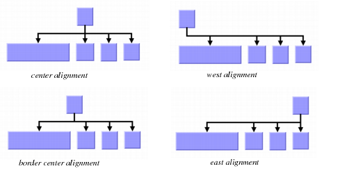
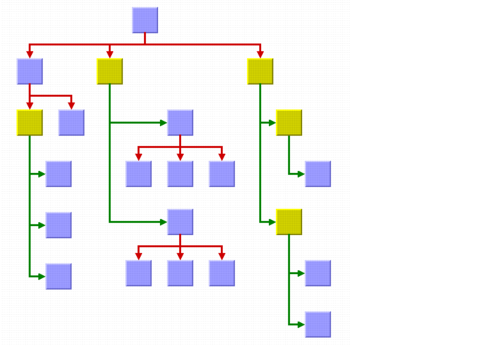
The alignment option controls how a parent is placed relative to its children. The alignment can be set globally, in which case all nodes are aligned in the same way, or locally on each node, with the result that different alignments occur in the same drawing.
Figure 4.6 Alignment Options
Global Alignment
To set the global alignment, use the following method:
The valid values for alignment are:
 IlvLayoutCenterAlignment
 (the default)
The parent is centered over its children, taking the center of the children into account.
 IlvLayoutBorderCenterAlignment
The parent is centered over its children, taking the border of the children into account. If the size of the first and the last child varies, the border center alignment places the parent closer to the larger child than the default center alignment.
 IlvLayoutEastAlignment
The parent is aligned with the border of its easternmost child. For instance, if the flow direction is to the bottom, east is the direction to the right. If the flow direction is to the top, east is the direction to the left. See
Compass Directions for details.
 IlvLayoutWestAlignment
The parent is aligned with the border of its westernmost child. For instance, if the flow direction is to the bottom, west is the direction to the left. If the flow direction is to the right, west is the direction to the bottom. See
Compass Directionsfor details.
 IlvLayoutTipOverAlignment
The children are arranged sequentially instead of in parallel, and the parent node is placed with an offset to the children. For details see
Tip-over Alignment.
 IlvLayoutMixedAlignment
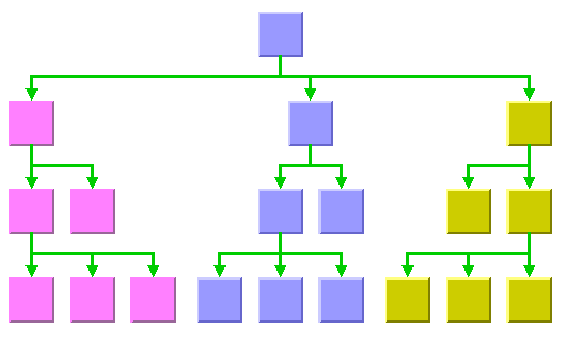
Each parent node can have a different alignment. In this case the alignment of each individual node can be set, with the result that different alignments can occur in the same graph.
To obtain the current choice, use the following method:
Alignment of Individual Nodes
All nodes have the same alignment unless the global alignment is set to IlvLayoutMixedAlignment. Only when the global alignment is set to “mixed” can each node have an individual alignment style.
Figure 4.7 Different Alignments Mixed in the Same Drawing
To set and retrieve the alignment of an individual node, use the following methods:
void setAlignment(IlAny node, IlvLayoutAlignment alignment); The valid values for the individual alignments of a node are:
 IlvLayoutCenterAlignment
 (the default)
 IlvLayoutBorderCenterAlignment
 IlvLayoutEastAlignment
 IlvLayoutWestAlignment
 IlvLayoutTipOverAlignment
Tip-over Alignment
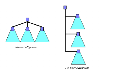
Normally the children of a node are placed in a parallel arrangement with siblings directly neighbored to each other. Tip-over alignment means a sequential arrangement of the children instead.
Figure 4.8 Normal Alignment and Tip-over Alignment
Tip-over alignment is useful if the tree has many leaves. With normal alignment, this would result in the layout being very wide. If the global alignment style is tip-over, the drawing is very high instead. In order to balance the width and height of the drawing, you can set the global alignment to “mixed”:
and the individual alignment to “tip-over” for some parents with a high number of children:
Tip-over alignment can be specified explicitly for some (or all) nodes. Furthermore, the Tree Layout offers layout modes that automatically determine when to tip over, yielding a drawing fit to a given aspect ratio. These layout modes are described in
Tip-Over Layout Modes.
Figure 4.9 Tip-over Alignment
Tip-over alignment works very well with the
Orthogonal Link Layout.
Link Style
When the layout algorithm moves the nodes, straight-line links—such as instances of
IlvLinkImage—will automatically “follow” the new positions of their end nodes. If the grapher contains other types of links (for example,
IlvPolylineLinkImage or
IlvDoubleSplineLinkImage), the shape of the link may not be appropriate because the intermediate points of the link will not be moved. In this case, you can ask the layout algorithm to automatically remove all the intermediate points of the links (if any). Also, you can specify that the links be reshaped into an “orthogonal” form. You can set the link style globally, in which case all links have the same kind of shape, or locally on each link, in which case different link shapes occur in the same drawing.
Note: The layout algorithm calls the method ensureReshapeableLinks on the attached graph model to ensure that all the links can be reshaped as needed. With an IlvGrapher, this method may replace links with the appropriate type of link and install the appropriate link connector on the nodes. For details on the graph model, see Using the Graph Model. |
Global Link Style
To set the global link style, the following method is provided:
The valid values for style are:
 IlvLayoutNoReshapeLinkStyle
 None of the links is reshaped in any manner.
 IlvLayoutStraightLineLinkStyle
 All the intermediate points of the links (if any) are removed. This is the default value. See
Figure 4.1 and
Figure 4.3 as examples.
 IlvLayoutOrthogonalLinkStyle
 The links are reshaped in an orthogonal form (alternating horizontal and vertical segments). See
Figure 4.2 and
Figure 4.9 as examples.
 IlvLayoutMixedLinkStyle
 Each link can have a different link style. In this case, the style of each individual link can be set to have different link shapes occurring on the same graph.
To obtain the current choice, use the following method:
IlvLayoutLinkStyle getLinkStyle() const;
Individual Link Style
All links have the same style of shape unless the global link style is IlvLayoutMixedStyle. Only when the global link style is set to “mixed” can each link have an individual link style.
Figure 4.10 Different Link Styles Mixed in the Same Drawing
To set and retrieve the style of an individual link, use the following methods:
The valid values for the individual alignments of a node are:
 IlvLayoutStraightLineLinkStyle
 (the default)
 IlvLayoutNoReshapeLinkStyle
  IlvLayoutOrthogonalLinkStyle
 Note: The link style of a Tree Layout graph requires links in an IlvGrapher that can be reshaped. Links of type IlvLinkImage, IlvOneLinkImage, IlvDoubleLinkImage, IlvOneSplineLinkImage, and IlvDoubleSplineLinkImage cannot be reshaped. You can use the class IlvPolylineLinkImage instead. |
Spacing Parameters
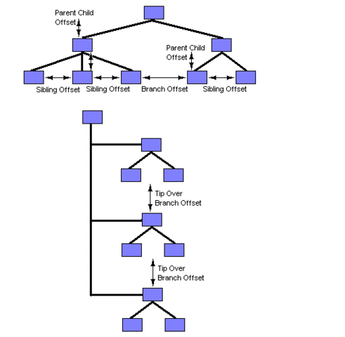
The spacing of the layout is controlled mainly by three spacing parameters: the distance between a parent and its children, the minimal distance between siblings, and the minimal distance between nodes of different branches. For instance, if the flow direction is to the top or bottom, the offset between parent and children is vertical, while the sibling offset and the branch offset are horizontal.
For tip-over alignment, there is a fourth spacing parameter: the minimal distance between branches starting at a node with tip-over alignment. This offset is always orthogonal to the normal branch offset, that is, if the flow direction is to the top or bottom, the tip-over branch offset is vertical.
Figure 4.11 Spacing Parameters
The spacing parameters can be set by the following methods:
They can be obtained by the corresponding methods:
For Experts: Further Spacing Parameters
If the link style is orthogonal, the shape of the links from the parent to its children looks like a fork (see
Figure 4.7). The position of the bend points in this shape can be influenced by the
orthogonal fork percentage, a value between 0 and 100. This is a percentage of the parent child offset. If the orthogonal fork percentage is 0, the link shape forks directly at the parent node. If the percentage is 100, the link shape forks at the child node. A good choice is between 25 and 75. This percentage can be set and obtained by the following methods:
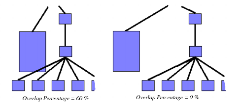
If the link style is not orthogonal, links may overlap neighboring nodes. This happens only in very few cases, for instance, if a link starts at a very small node that is neighbored by a huge node. This deficiency can be fixed by increasing the branch offset. However, this influences the layout globally, affecting nodes without that deficiency. To avoid a global change, you can change the overlap percentage instead, which is a value between 0 and 100. This value is used by an internal heuristic of the layout algorithm that considers a node to be smaller by this percentage. The default percentage is 30. This usually results in a better usage of the space. However, if very small nodes are neighbored to huge nodes, it is recommended decreasing the overlap percentage or setting it to 0 to switch this heuristic off to avoid links overlapping nodes. The overlap percentage can be set and obtained by the following methods:
Tip: It is recommended that you always set the orthogonal fork percentage to a larger value than the overlap percentage. |
Figure 4.12 The Effect of the Overlap Percentage
Version 6.0
Copyright © 2015, Rogue Wave Software, Inc. All Rights Reserved.
