Drawing the Prototype
Define the graphic presentation of your prototype using the Prototype buffer window:

You can drag and drop graphic objects into the buffer and use the editing modes to create lines, polygons, and so on: a Prototype buffer window has all the properties of the Rogue Wave Views Studio 2D Graphics buffer window.
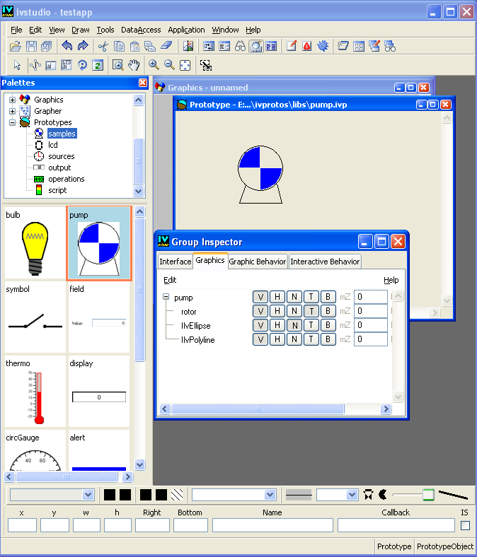
As you draw your prototype, you can see its structure in the Graphics page of the Group Inspector panel, shown in addition to the Main window.
Figure 2.1 shows an example of this. The list of graphic nodes appears organized from bottom to top. As you add graphic objects to the prototype, the tree structure is updated. You can select graphic nodes either directly in the Prototypes buffer window (as you do in Rogue Wave Views Studio) or in the tree that appears in the Group Inspector panel.
Figure 2.1 The Graphics Notebook Page of the Group Inspector Panel
Editing Prototype Nodes
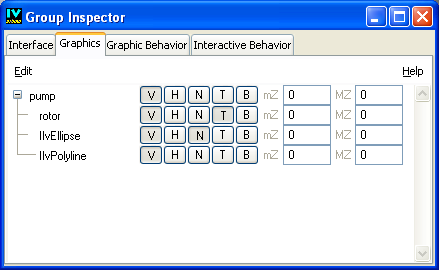
You can use the fields on the Graphics page of the Group Inspector (see
Figure 2.2) to change a number of properties associated with the elements (or nodes) in your prototypes:
Figure 2.2 The Graphics Notebook Page of the Group Inspector Panel
If the selected node is a graphic node, the properties only apply to this particular node.
If the selected node is a group node—that is, the root node of the prototype, a subgroup of the prototype, or a prototype instance—the properties apply to all the child graphic nodes of the selected group.
The following table describes the fields found on the Graphics notebook page:
Fields of the Graphics Notebook Page of the Group Inspector Panel
Field | Description |
Node name | This text field is used to change the name of the node. You can also use the Name field of the Generic Inspector in the Rogue Wave Views Studio Main window. Note: Nodes should contain only alpha-numeric characters (A-Z, a-z, 0-9). |
(V) Visible | This toggle controls the visibility of the graphic object in the prototype. |
(H) Hidden in application | If this button is set, the selected graphic object is visible only while editing the prototype or its instances in Rogue Wave Views Studio. The object is hidden in the final application. This property can be used to create intermediate “computing” prototype instances such as those of the “operations” prototype library. |
(N) Grapher node | If this button is set, the graphic object is added as a grapher node when the prototype is instantiated in a grapher. This allows you to use prototype instances as grapher nodes. (This button is deprecated and included for compatibility reasons.) |
(T) Transformed | This button controls whether a transformer is associated with the graphic node to ensure that the graphic object can be transformed arbitrarily without distortions. Without a local transformer, some Rogue Wave Views objects lose their original geometry when they are resized. Using a local transformer ensures that the geometry of objects is not modified by geometric transformations. On the other hand, using a local transformer consumes more memory. If you select this button, remember that you must use the standard Selection mode to inspect the graphic object of the node. If you use the Group Selection mode, the selected object is an instance of a subclass of IlvTransformedGraphic and cannot be inspected. |
(B) Bounded Size | If set, this flag restricts the zoomability of the objects. Setting this flag and leaving mZ and MZ to 0 is equivalent to setting both of them to 1. It is, however, more efficient. If Bounded Size is set, and mZ or MZ are not 0, this flag makes the objects disappear if the zoom factor of the view of the instance is greater than MZ or less than mZ. |
(mZ) Min. Zoom | If not zero, this attribute limits the minimum size an object can have. When the scaling factor of the view holding the object is below this value, the object does not get any larger. If Min. Zoom and Max. Zoom are set to the same value, the object never grows or shrinks in size. If they are set to 1, they stay at the size at which they were created. |
(MZ) Max. Zoom | If not zero, this attribute limits the maximum size an object can have. When the scaling factor of the view holding the object is above this value, the object does not get any larger. |
Structuring Prototype Nodes
To structure your prototype, you can group graphic nodes into subgroups. This may be useful when you define your prototype accessors; for example, when you want to rotate a group of objects or change their color. To create a subgroup:
1. In the Prototype buffer window, select the graphic objects you want to group.
2. From the Draw menu select Group.
The objects are grouped into an instance of the class
IlvGroup and a subgroup node is created in the prototype. The node tree shows the structure change.
Using the Group Selection mode, subgroups can be selected and moved as a whole. This mode shows the selected group by drawing a dashed-line frame around the group. You are still able to select individual graphic objects inside subgroups with the standard Selection mode.
To include instances of other prototypes in the prototype you are editing:
1. If not already open, activate the Prototypes palette by choosing Palettes from the Tools menu.
2. Select the desired prototype library.
3. Drag and drop the prototype into the Prototype buffer window. The Nodes page of the Prototype Inspector will show a new node, similar to a subgroup node, for the prototype instance.
Having added objects, you may return to the Interface page to define new attributes that reference the internal nodes, or go to the Behavior page to define dynamic behaviors for the prototype.
Version 5.8
Copyright © 2014, Rogue Wave Software, Inc. All Rights Reserved.