Parameters
The Hierarchical Layout uses generic parameters, common to other graph layouts, and specific parameters applicable in hierarchical layouts only. Refer to the following sections for general information on parameters among the graph layouts:
The Hierarchical Layout parameters are described in detail in this topic under:
Generic Parameters
The
IlvHierarchicalLayout class supports the following generic parameters defined in the
IlvGraphLayout class:
The following paragraphs describe the particular way in which these parameters are used by this subclass.
Allowed Time
The layout algorithm stops if the allowed time setting has elapsed. (For a description of this layout parameter in the
IlvGraphLayout class, see
Allowed Time.) If the layout stops early because the allowed time elapsed, the nodes and links are not moved at all and remain in the same position they had before the call of layout.
Preserve Fixed Links
The layout algorithm does not reshape the links that are specified as fixed. (For more information on link parameters in the
IlvGraphLayout class, see
Preserve Fixed Links and
Link Style.)
Preserve Fixed Nodes
The layout algorithm does not move the nodes that are specified as fixed. (For more information on node parameters in the
IlvGraphLayout class, see
Preserve Fixed Nodes.) Moreover, the layout algorithm ignores fixed nodes completely and also does not route the links that are incident to the fixed nodes. This can result in undesired overlapping nodes and link crossings. However, this feature is useful for individual, disconnected components that can be laid out independently.
Specific Parameters
The following parameters are specific to the
IlvHierarchicalLayout class:
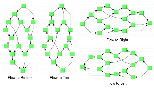
Flow Direction
The flow direction parameter specifies the direction in which the majority of the links should point. If the flow direction is to the top or to the bottom, the node levels are oriented horizontally and the links mostly vertically. If the flow direction is to the left or to the right, the node levels are oriented vertically and the links mostly horizontally.
If the flow direction is to the bottom, the nodes of the level with index 0 are placed at the top border of the drawing. The nodes with level index 0 are usually the root nodes of the drawing (that is, the nodes without incoming links). If the flow direction is to the top, the nodes with level index 0 are placed at the bottom border of the drawing. If the flow direction is to the right, the nodes are placed at the left border of the drawing.
Figure 4.27 Flow Directions
To specify the flow direction, use the following method:
The valid values for direction are:
 IlvRight
 (the default)
IlvLeft IlvBottom IlvTop To obtain the current choice, use the following method:
Level Justification
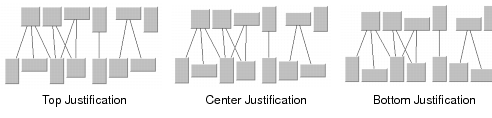
If the layout uses horizontal levels, the nodes of the same level are placed approximately at the same y-coordinate. The nodes can be justified, depending on whether the top border, or the bottom border, or the center of all nodes of the same level should have the same y-coordinate.
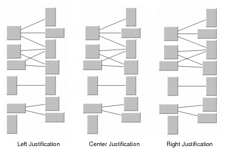
If the layout uses vertical levels, the nodes of the same level are placed approximately at the same x-coordinate. In this case, the nodes can be justified to be aligned at the left border, at the right border, or at the center of the nodes that belong to the same level.
To specify the level justification, use the following method:
If the flow direction is to the top or to the bottom, the valid values for justification are:
IlvTop IlvBottom IlvCenter (the default)
Figure 4.28 Level Justification for Horizontal Levels
If the flow direction is to the left or to the right, the valid values for justification are:
IlvLeft IlvRight IlvCenter (the default)
Figure 4.29 Level Justification for Vertical Levels
To obtain the current value, use the following method:
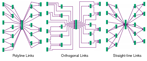
Link Style
The layout algorithm positions the nodes and routes the links. To avoid overlapping nodes and links, it creates bend points for the shapes of links. The link style parameter controls the position and number of bend points. The link style can be set globally, in which case all links have the same kind of shape, or locally on each link such that different link shapes occur in the same drawing.
Figure 4.29 Link Styles
Note: The layout algorithm calls the method ensureReshapeableLinks on the attached graph model to ensure that all the links can be reshaped as needed. With an IlvGrapher, this method may replace links with the appropriate type of link and install the appropriate grapher pin on the nodes. For details on this method, see the Reference Manual. For details on the graph model, see the section Using the Graph Model. |
Global Link Style
To set the global link style, use the following method:
The valid values for style are:
IlvLayoutPolylineLinkStyle All links get a polyline shape. A polyline shape consists of a sequence of line segments that are connected at bend points. The line segments can be turned into any direction. This is the default value.
IlvLayoutOrthogonalLinkStyle All links get an orthogonal shape. An orthogonal shape consists of orthogonal line segments that are connected at bend points. An orthogonal shape is a polyline shape where the segments can be turned only in directions of 0, 90, 180 or 270 degrees.
IlvLayoutStraightLineLinkStyle All links get a straight-line shape. All intermediate bend points (if any) are removed. This often causes overlapping nodes and links.
IlvLayoutNoReshapeLinkStyle None of the links is reshaped in any manner.
IlvLayoutMixedLinkStyle Each link can have a different link style. In this case, the style of each individual link can be set such that different link shapes can occur in the same graph.
To obtain the current choice, use the following method:
Individual Link Style
All links have the same style of shape unless the global link style is MIXED_STYLE. Only when the global link style is MIXED_STYLE can each link have an individual link style.
Figure 4.30 Different Link Styles Mixed in the Same Drawing
To set and retrieve the style of an individual line, use the following methods:
The valid values for the local link style are the same as for the global link style:
IlvLayoutPolylineLinkStyle IlvLayoutOrthogonalLinkStyle IlvLayoutStraightLineLinkStyle IlvLayoutNoReshapeLinkStyle Note: The link style of the Hierarchical Layout requires links in an IlvGrapher that can be reshaped. Links of type IlvLinkImage, IlvOneLinkImage, IlvDoubleLinkImage, IlvOneSplineLinkImage and IlvDoubleSplineLinkImage cannot be reshaped. You can use the class IlvPolylineLinkImage instead. |
Connector Style
The layout algorithm positions the end points of links (the connector pins) at the nodes automatically. The connector style parameter specifies how these end points are calculated.
Figure 4.31 Connector Styles
To set the connector style, use the following method:
The following options are available for style:
IlvLayoutCenteredPins The end points of the links are placed in the center of the border where the links are attached. This option is well-suited for polyline links and straight-line links. It is less well-suited for orthogonal links, because orthogonal links can look ambiguous in this style.
IlvLayoutClippedPins Each link pointing to the center of the node is clipped at the node border. The connector pins are placed at the points on the border where the links are clipped. This option is particularly well-suited for polyline links.
IlvLayoutEvenlySpacedPins The connector pins are evenly distributed along the node border. This style guarantees that the end points of the links do not overlap. This is the best style for orthogonal links and works well for other link styles.
IlvLayoutAutomaticPins The connector style is selected automatically depending on the link style. If any of the links have an orthogonal style, the algorithm chooses evenly spaced connectors. If all the links are straight, it chooses centered connectors. Otherwise, it chooses clipped connectors.
To obtain the current choice, use the following method:
Note: The connector style parameter requires grapher pins at the nodes of an IlvGrapher that allow connector pins to be placed freely at the node border. It is recommended that you install IlvRelativeLinkConnector at nodes that are contained in an IlvGrapher. |
Link Priority
The layout algorithm tries to place the nodes such that all links are short, point in the flow direction, and do not cross each other. However, this is not always possible. Often, links cannot have the same length. If the graph has cycles, some links must be reversed against the flow direction. If the graph is nonplanar, some links have to cross each other.
The link priority parameter controls which links should be selected if long, reversed, or crossing links are necessary. Links with a low priority are more likely to be selected than links with a high priority. This does not mean that low-priority links are always longer, reversed, or crossed, because the graph may have a structure such that no long, reversed or crossing links are necessary.
To set or retrieve the link priority, use the following methods.
The default value of the link priority is 1.0. Negative link priorities are not allowed.
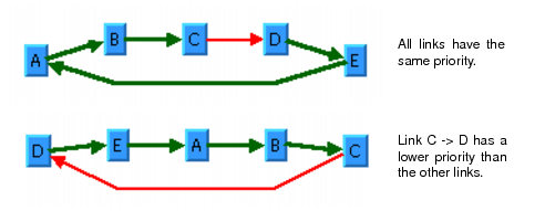
For an example of using the link priority, consider a cycle A->B->C->D->E->A. It is impossible to lay out this graph without reversing any link. Therefore, the layout algorithm selects one link to be reversed. To control which link is selected, you can give one link a lower priority than the others. This link will be reversed. In
Figure 4.32, the bottom layout shows the use of the link priority. The link C->D was given the priority 0.5, while all the other links have the priority 1.0. Therefore C-D is reversed. The top layout in
Figure 4.32 shows what happens when all links have the same priority. Link E->A is reversed.
Figure 4.32 Working With Link Priorities
Level Index
In Step 1 of the layout algorithm (the leveling phase), the nodes are partitioned into levels. These levels are indexed starting from 0. For instance, when the flow direction is to the bottom, the nodes of the level with index 0 are placed at the topmost horizontal level line, and the nodes with larger level index are placed at a lower position than the nodes with smaller level index (see
Figure 4.26). The layout algorithm calculates these level indices automatically.
You can affect how the levels are partitioned by specifying the level indices for some nodes. The nodes are placed in the specified level.
To specify the level index of a node, use the following method:
The default value is -1. If the default value is used or if a node is set to a negative level index, the layout algorithm automatically calculates an appropriate level index during the leveling phase of the algorithm.
To obtain the current level for a node, use the following method:
Warning: Using arbitrarily large level indices is not recommended. For instance, if you set the level index of a node to 100000, the layout algorithm would create 100,000 levels even if the graph has much fewer nodes. This would cause the layout algorithm to become unnecessarily slow. |
Figure 4.33 illustrates a hierarchical layout with the same level specified for each node of the graph.
Figure 4.33 All Nodes Fixed at Same Level
Position Index
In Step 2 of the layout algorithm (the crossing reduction phase), the nodes are ordered within the levels. All nodes that belong to the same level get a position index starting from 0. For instance, when the flow direction is to the bottom, the node with the position index 0 is placed in the left-most position within its level. The nodes with a larger position index are placed more to the right than the nodes with a smaller position index in the same level. The nodes of different levels are independent. The node of the first level with the position index 0 is left of the node of the first level with the position index 1, but not necessarily left of a node of another level with position index 0. Note that long links crossing a level also obtain a position index (see
Figure 4.26). The layout algorithm calculates these position indices automatically.
You can affect how the nodes are positioned within each level by specifying the position index of some nodes. The nodes are placed at the specified position within their level.
To specify the position index of a node, use the following method:
The default value is -1. If the default value is used, if a node is set to a negative position index, or if a node is set to a position index that is larger than the number of nodes of its level, the layout calculates automatically an appropriate position index during the crossing reduction step.
To obtain the current position index of a node, use the following method:
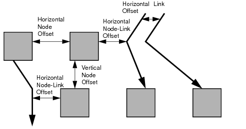
Spacing Parameters
The spacing of the layout is controlled by three kinds of spacing parameters: the minimal offset between nodes, the minimal offset between parallel segments of links and the minimal offset between a node border and a bend point of a link or a link segment that is parallel to this border. The offset between parallel segments of links is at the same time the offset between bend points of links. All three kind of parameters occur in both directions: horizontally and vertically.
Figure 4.34 Spacing Parameters
The spacing parameters can be set for the horizontal direction by the following methods:
The spacing parameters can be set for the vertical direction by the following methods:
The spacing parameters can be obtained by the corresponding methods:
For a layout with horizontal levels (the flow direction is to the top or to the bottom), the horizontal node offset is the minimal distance between nodes of the same level. The vertical node offset is the minimal distance between nodes of different levels, that is, the minimal distance between the levels. For non-orthogonal link styles, the horizontal link offset is basically the minimal distance between bend points of links. The horizontal node-link offset is the minimal distance between the node border and the bend point of a link. For horizontal levels, the vertical link offset and the vertical node-link offset play a role only if the link shapes are orthogonal.
Similarly, for a layout with vertical levels (the flow direction is to the left or to the right), the vertical node offset controls node distances within the levels. The horizontal node offset is the minimal distance between the levels. In this case, the vertical link offset and the vertical node-link offset always play a role, while the horizontal link offset and the horizontal node-link offset affect the layout only with orthogonal links.
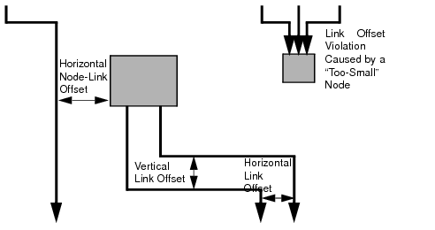
For orthogonal links, the horizontal link offset is the minimal distance between parallel, vertical link segments. The vertical link offset is the minimal distance between parallel, horizontal link segments. However, the layout algorithm cannot always satisfy these offset requirements. If a node is very small but has many incident links, it may be impossible to place the links orthogonally with the specified minimal link distance on the node border. In this case, the algorithm places some link segments closer than the specified link offset.
Figure 4.35 Spacing Parameters for Orthogonal Links
Sequences of Graph Layout
In some circumstances, you may need to use a sequence of layouts on the same graph. For example:
You work with graphs that become out-of-date and need to extend the graph. If you perform a layout on the extended graph, you probably want to identify the parts that were already laid out in the original graph. The layout should not change very much when compared to the layout of the original graph.
The first layout results in a drawing with minor deficiencies. You want to solve these deficiencies manually and perform a second layout to clean up the drawing. For the parts of the graph that were already acceptable after the first layout, the second layout probably should not change them very much.
The Hierarchical Layout supports sequences of layout that “do not change very much.” It allows you to preserve the level index of a node and the position index of the node within the level. By doing this, the relative position of a node compared to a previous layout does not change. The algorithm calculates new coordinates for the nodes and new routings for the links to adjust the absolute positions of the objects in order to clean up the drawing. The relative order such as “node A is in a level above node B” or “node A is left of node B” can be preserved.
The parameters for hierarchical sequences are described in:
Calculated Level Index
The layout algorithm allows you to access the level index that was calculated for a node by a previous layout. To do this, use the following method:
If the node was never laid out, this method returns -1. Otherwise, it returns the previous level index of the node.
The method can be used to specify the level index for the next layout in the following way:
IlInt index = layout->getCalcNodeLevelIndex(node); layout->setSpecNodeLevelIndex(node, index); |
When this is done, it ensures that the node is placed at the same level as in the previous layout.
If the graph is detached from the layout algorithm, the calculated level index of a node is set back to -1.
Note: You should be aware of the difference between the methods getCalcNodeLevelIndex and getSpecNodeLevelIndex. The first one returns the level index calculated by the previous layout. The second one returns the specified level index, even if there was no previous layout. For instance, consider two nodes A and B. Node A has no specified level index and node B has a specified level index 5. Before the first layout, the method IlvHierarchicalLayout::getCalcNodeLevelIndex returns -1 for both nodes because the levels have not been calculated yet. However, IlvHierarchicalLayout::getSpecNodeLevelIndex returns -1 for A and 5 for B. After the first layout, node A may be placed at level 4. Now, IlvHierarchicalLayout::getCalcNodeLevelIndex returns 4 for node A and 5 for node B and IlvHierarchicalLayout::getSpecNodeLevelIndex still returns -1 for A and 5 for B. |
Calculated Position Index
The layout algorithm allows you to access the position index within a level that was calculated for a node by a previous layout. To do this, use the following method:
If the node was never laid out, this method returns -1. Otherwise, it returns the previous position index of the node within its level.
To ensure that the node is placed at the same level at the same relative position as in the previous layout, use the following:
layout->setSpecNodeLevelIndex(node, layout->getCalcNodeLevelIndex(node)); layout->setSpecNodePositionIndex(node, layout->getCalcNodePositionIndex(node)); |
If the graph is detached from the layout algorithm, the calculated position index of a node is set back to -1.
Note: You should be aware of the difference between the methods getCalcNodePositionIndex and getSpecNodePositionIndex. The first one returns the position index calculated by the previous layout and -1 if there was no previous layout. The second one returns the specified position index, even if there was no previous layout. This behavior is similar to the behavior of the specified and calculated level index (see the section Calculated Level Index). |
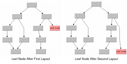
Layout Refinements
The following example shows how to use the calculated and specified level and position indices to refine a layout. Assume that you want to place a leaf node in the level with the highest index (see
Figure 4.36). Since you do not know before laying out the graph how many levels will be created, you cannot specify the highest level index at the beginning. You must perform a first layout, iterate over the nodes, and retrieve the highest calculated level. If the leaf node is not already placed at the highest level index, you must specify this level index for the leaf node while preserving the level and position indices of all other nodes. Then perform the layout a second time. The following code fragment shows how to do this.
// ... IlvHierarchicalLayout* layout = new IlvHierarchicalLayout(); layout->attach(grapher); // perform a first layout IlvGraphLayoutReport* layoutReport = layout->performLayout(); // ... // calculate the maximal level index, and preserve the relative node positions // for the next layout IlInt maxLevelIndex = -1; IlUInt count; IlvGraphic* const* allObjects = grapher->getObjects(count); for (i = 0 ; i < count ; ++i) { IlvGraphic* node = allObjects[i]; if (grapher->isNode(node)) { IlInt levelIndex = layout->getCalcNodeLevelIndex(node); IlInt positionIndex = layout->getCalcNodePositionIndex(node); if (maxLevelIndex < levelIndex) maxLevelIndex = levelIndex; layout->setSpecNodeLevelIndex(node, levelIndex); layout->setSpecNodePositionIndex(node, positionIndex); } } // if the leaf node was not at maximal level index, specify the maximal // level index for the leaf node and perform layout again if (layout->getCalcNodeLevelIndex(leafnode) != maxLevelIndex) { layout->setSpecNodeLevelIndex(leafnode, maxLevelIndex); layout->setSpecNodePositionIndex(leafnode, -1); layoutReport = layout->performLayout(); // ... } layout->detach(); delete layout; |
Figure 4.36 Moving the Leaf Node to the Lowest Level (Highest Level Index)
Version 5.8
Copyright © 2014, Rogue Wave Software, Inc. All Rights Reserved.