Level Layout Mode
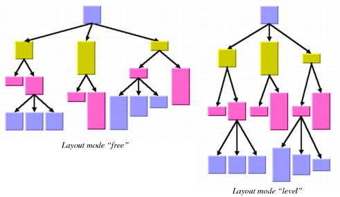
The level layout mode partitions the node into levels and arranges the levels horizontally or vertically. The root is placed at level 0, its children at level 1, the children of those children at level 2, and so on. In contrast to the free layout mode, in level layout mode the nodes of the same level are justified with each other even if they are not siblings (that is, they do not have the same parent).
Figure 4.13 shows the same graph in free layout mode and in level layout mode.
The following statement sets the level layout mode:
layout->(IlvTreeLayoutLevelMode); Figure 4.13 Free Layout Mode and Level Layout Mode
Additional parameter information for level tree layout is as follows:
General Parameters
Most layout parameters that work for the free layout mode work as well for the level layout mode. You can set the flow direction, the spacing offsets, the global or individual link style, and the global or individual alignment. See
Free Layout Mode for details.
The differences from the free layout mode are:

The tip-over alignment does not work in level layout mode.

The parent-child offset parameter controls the spacing between the levels. In level layout mode, it is the minimal distance between parent and its children, while in free layout mode, it is the exact distance between parent and its children.

The overlap percentage has no effect in level layout mode.
Level Justification
In level layout mode with flow direction to the top or bottom, the nodes are organized in horizontal levels such that the nodes of the same level are placed approximately at the same y-coordinate. The nodes can be justified, depending on whether the top border, the bottom border, or the center of all nodes of the same level should have the same y-coordinate.
In flow direction to the left or right, the nodes are organized in vertical levels approximately at the same x-coordinate. The nodes of the same level can be justified at the left border, at the right border, or at the center.
To distinguish the justification independently from the flow direction, we use the directions north and south (see section
Compass Directions). The north border of a node is the border that is closer to the level where its parent is placed, and the south border of a node is the border that is closer to the level where its children are placed. If the flow direction is to the bottom, the level justification north means that the nodes are justified at the top border, and south means that the nodes are justified at the bottom border. If the flow direction is to the top, it is converse: north means the bottom border and south means the top border. If the flow direction is to the right, then north means the left border and south means the right border.
Figure 4.14 Level Justification
To specify the level justification, use the following method:
void (IlvLayoutAlignment justification); To obtain the current value, use the method:
IlvLayoutAlignment () const; The valid choices for the justification are:
 IlvLayoutCenterAlignment
 (the default)
 IlvLayoutNorthAlignment
 IlvLayoutSouthAlignment
Version 5.5.1
Copyright © 2012, Rogue Wave Software, Inc. All Rights Reserved.


