Predefined business objects
Introduces the predefined business objects provided by JViews TGO.

Presents the different kinds of network elements and their graphical representation.

Provides some examples of links and their graphical representation.

Explains what a group is and presents the different kinds of groups and their graphical representation.

Defines the concept of subnetwork and shows the two possible ways to display a subnetwork.

Defines and illustrates the concepts of shelves, cards, ports, and LEDs.

Defines the concept of base transceiver station.

Describes what off-page connectors are used for.

Describes the specificity of the
JViews TGO alarm object.
Network elements
Network elements include any kind of shelf-based telecom or data-communications equipment (a switch, a multiplexer, a cross-connect, and so on), outside plant equipment (coax node), and peripheral equipment (terminal or printer).
Network element representations
A network element can be represented by a pictorial representation (bitmap image or vector drawing), a symbol, or a shape. Not all physical details of the element are visible in the representation.
 Pictorial representation
.The network element base is a bitmap image or vector drawing. This drawing is meant to be realistic. Several predefined bases are available for shelf-based equipment, terminals, and mobile phone access network elements. New bases can easily be introduced by providing bitmap images.
Pictorial representations of shelf-based equipment and terminal
 Symbolic representation
. The network element base has a square and the network element function is denoted by a symbol containing ITU/ANSI or traditional symbols. The default type corresponding to the default symbolic network element representation is called NE (Network Element). The following figure illustrates an NE type network element: here, an add-drop multiplexer with a capacity of OC192.
Symbolic representation of NE type network element
 Shape representation
. The network element base has a geometric shape that symbolizes the network element type (or function class). The center of the base may contain an icon that further refines the network element function. Several predefined shapes are provided as types of the network elements. The following figure illustrates a Mux shape network element.
Shape representation of mux network element
Partial network elements
A partial network element is an abstraction which denotes a network element that is only part of the real-world network element. Partial network elements can be used in several situations, for example:

To represent distributed clusters where parts of a cluster need to be divided across different subnetworks.

To allow one network element to be used by different service providers. In this case, the network element needs to be divided in several parts. Each part is represented as a partial network element and its state reflects only the elements that are interesting for the service provider that is using it.
Partial network elements are graphically represented by an icon located at the bottom left of the network element base.
Partial network elements expanded and collapsed
Shortcuts
A shortcut network element is an abstraction denoting an object that is only a reference to an existing network element.
Shortcuts can be either standard or dangling. In the first case, the network element is a shortcut to another object that is managed by the system. In the second case, the network element is a shortcut to an object that is currently not available, which means that the shortcut is dangling and needs to be validated by the management system.
Shortcut network elements are graphically represented by an icon located at the bottom left of the network element base.
Standard shortcuts
Sample links
For more information about network elements, see
Network elements.
Links
Links are used to display the transmission elements making up the network lines.
Links feature the same dynamic display as network elements. Each type of link has its own graphical representation, and different link states are represented graphically by changes in color or internal pattern design. Links can also carry decorations, in particular to represent alarms. Links can be directional.
Some sample links are shown in the following figure.
| A link in the disabled state. |
| A link in the active state. |
| A link with secondary states and a label. |
| A link with an alarm cluster. |
The drawing of a link between two nodes is, by default, automatically calculated by JViews TGO. The link calculation is performed using a layout optimizer.
The default layout optimizer provided draws direct links without intermediate points and according to a given angle. The links are attached to nodes using small horizontal or vertical segments.
For more information about links, see
Links.
Links can also be grouped in a link bundle, that is, a set of links that have the same destination node. Links in a bundle can be collapsed to a single overview link.
Groups
Groups are containers that logically group network resources. They are used to display a geographic or a functional region by grouping together either network elements (such as multiplexers, switches, and so on) or links (such as transport, access, and so on).
Groups support the whole set of state and alarm representations: alarm balloons, severity color, primary state representation graphics, status or secondary state icons, and so forth.
Groups have three kinds of visual representations: polygonal, rectangular, and linear.
Polygonal groups
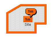
Polygonal groups are flexible containers that generally represent a group of network elements at a regional level. Polygonal groups usually do not represent a physical object, but rather a user-defined collection of objects that are not necessarily located in the same place. Polygonal groups are represented by a screened transparent polygon with a relief border as shown in the following figure.
Polygonal group with single minor alarm
In this figure the group label, the alarm counter, and the alarm balloon are displayed as a cluster. The drawing of this cluster is organized around a central rectangle called a plinth which is drawn by default at the polygon center.
Rectangular groups
Rectangular groups hold network elements that are located in the same place such as a site, a building, or a city. They can be resized to create any kind of rectangular container. Rectangular groups look like an opaque relief rectangle, as shown in the following figure.
Rectangular group with single warning alarm
Rectangular groups with alarms contain an information cluster located by default at the center of the rectangle.
Linear groups
Linear groups are bendable, “pipe-like” containers. They are used to hold a group of network elements and links or they may represent the backbone transport system in the network. The graphical representation of linear groups evokes a linear collection of objects. For example, linear groups can be used to represent all the repeaters between two line termination network elements.
The following figure shows an example of a linear group on which a critical alarm has been detected.
Linear group with single critical alarm
When an alarm is displayed on a linear group, an information cluster appears at the center of the median segment. The median segment is the segment containing the midpoint of the link.
Shortcuts
A shortcut group is an abstraction denoting an object that is only a reference to an existing group.
Shortcuts can be either standard or dangling. In the first case, the group is a shortcut to another object that is managed by the system. In the second case, the group is a shortcut to an object that is currently not available, which means that the shortcut is dangling and needs to be validated by the management system.
Shortcut groups are graphically represented by an icon located at the bottom left of the group plinth.
Standard shortcut
Dangling shortcut
For more information about groups, see
Groups.
Subnetworks
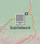
Subnetworks allow you to create applications that display a network inside another network. They are not pure predefined business objects in the sense that they are created automatically by the JViews TGO network component when you define a containment relationship between objects in the data source.
A subnetwork can be defined as any business object with child objects in the network component. You can display it either collapsed or expanded in the network component.

In the
collapsed state, the subnetwork is represented as a single object.
Collapsed subnetwork

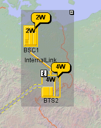
In the
expandedstate, the subnetwork is displayed with all the objects contained in it.
Expanded subnetwork
For more information about subnetworks, see
Subnetworks.
Shelves, cards, ports, and LEDs
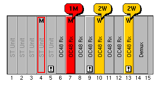
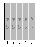
Shelves are telecom objects that can be made up of a certain number of slots of different widths in which cards can be stored. By default, slot numbers are displayed at the bottom of the slots.
Cards are represented by rectangles that support the same base states as network elements. Like network elements, they can carry alarm and status icons. They are used to display details of modifications that have been made to the states and alarms of an item of equipment at the level of the physical card.
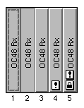
The following figure shows a shelf with empty slots (the first five) and cards in various states, some of them carrying alarms.
Shelf with cards in various states
By default, status and secondary state icons are displayed at the bottom of the card, and alarms at the top of the card. Only the letter corresponding to the highest outstanding alarm is displayed. Other counting information such as figures and + signs do not appear.
There are three different types of card:
 Standard cards
 correspond to the description given above. Such cards can take up one or several slots on the shelf and do not necessarily extend across an entire shelf section. You can, for example, place a card starting from slot #3 of the shelf and occupying this slot, the next slot and 50% of slot 5. Each card has its own label.
An example of a set of standard cards in various states (from disabled on the left to busy and shutting down on the right) is provided in the following figure.
Standard cards in various states
 Empty slots
 correspond to an empty portion of the shelf for which you want to display certain characteristics, either static (a label) or dynamic (statuses and alarms). The following figure shows a set of empty slots, where the basic design does not vary.
Empty slots
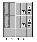
 Card-carrier cards
 hold other cards in a linear arrangement. All cards contained in the card carrier are the same size and can contain states, statuses, and alarms. The following figure shows a set of five card carriers, each of which carries two cards (in various states). The card carrier itself can carry statuses and alarms. The area at the bottom of the card carrier is used to display a graphic representation of its state.
Several card carriers with cards
Cards can contain ports and LEDs, which are called card items.
Ports are the physical interfaces of pieces of equipment and are usually located on cards, Ports can also be connectors.
Example of ports
LEDs (Light Emitting Diode) are used to represent the state of an item of equipment through a color. Most types of equipment use LEDs as interfaces to provide the user with information on hardware and software conditions.
Examples of LEDs
For more information about shelves and cards, see
Shelves and cards.
Base Transceiver Stations (BTS)
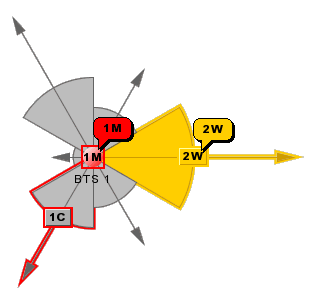
Base Transceiver Stations (BTS) are base stations composed of antennas that relay (receive and transmit) radio messages within cells of a cellular phone system.
Each antenna has an orientation and a beam width that are graphically represented. Each antenna can have its own state and graphical characteristics.
A BTS with three antennas
For more information about base transceiver stations, see
BTS (Base Transceiver Station).
Off-page connectors
Off-page connectors usually come in pairs and are used to show the continuation of a link from one network to another. They can be used in place of nodes (either groups or network elements) and can have links connected to them.
The following figure shows a partial network with three off-page connectors, each with a different graphic representation.
Network with different representations of off-page connectors
For more information about off-page connectors, see
Off-page connectors.
Alarms
The JViews TGO alarm object is based on the alarm object defined by the Java™ Specification Requests (JSR)-90 workgroup. This alarm object has been designed to be used in the development of OSS/J Quality of Service APIs (telecom management applications).
Alarms are of two kinds: raw and impact.
An alarm table with raw (balloons) and impact (clouds) alarms
A raw alarm is an alarm reported by a network element and carried by this element.
An impact alarm corresponds to a propagated alarm that is reported by a network element but carried by another element.
Alarms can be represented as individual objects in a table and tree. For more information, see
Alarms.
NOTE Alarms can also be represented as part of the managed object (in a network or equipment view). In this case, they are considered as part of the object state and not as individual objects. For more information, see
Alarm states.
Copyright © 2018, Rogue Wave Software, Inc. All Rights Reserved.


