Topological Mesh Layout (TML)
Gives information on the
Topological Mesh Layout (TML) algorithm (class
IlvTopologicalMeshLayout from the package
ilog.views.graphlayout.topologicalmesh).

Provides samples of the layout and explains where it is likely to be used.

Lists the features and limitations of the layout.

Gives an explanation of the concepts underlying TML, a brief description of the algorithm and a sample.

Describes the generic parameters supported by TML and explains the particular way in which these parameters are used by this subclass.

Describes the specific parameters supported by TML and gives samples of their use.

Describes how to refine the layout by fixing some nodes and avoiding overlapping nodes.

Describes the use of a link clipping interface.
General information on the TML
TML samples
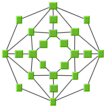
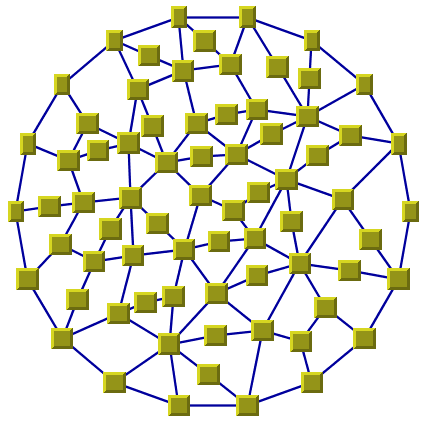
The following sample drawings were produced with TML.
Small cyclic graph drawing produced with TML
Large cyclic graph drawing produced with TML
What types of graphs suit the TML?

Cyclic (2-connected) graphs plus only a few branches. (You may need to make manual adjustments for the branches.)
Application domains for the TML
Application domains of the Topological Mesh Layout include:

Database and knowledge engineering (semantic networks, qualitative reasoning and other artificial intelligence diagrams)
Features and limitations of the TML
Features

Most of the time, produces planar drawings of planar graphs, and drawings with a small number of link crossings for nonplanar graphs.

Produces a nice layout for most small- and medium-size graphs relatively quickly. (The maximum
cyclomatic number of the graph is about 30-50, but the number of nodes and links can be a lot higher.)

Most of the time, produces symmetrical drawings of symmetrical graphs.

The computation time for one iteration depends on the cyclomatic number of the graph, which is smaller than the number of nodes or links.

The user can obtain several layouts of the same graph easily and quickly by simply changing a parameter (especially the starting node and the outer cycle) or by applying manual refinements to the layout. The best layout can then be selected from the resulting layouts.
Limitations

The algorithm tries to minimize the number of
link crossings (which is generally an
NP-complete problem). It is mathematically impossible to quickly solve this problem for any graph size. Therefore, the algorithm uses heuristics that cannot always obtain a layout with the theoretical minimum number of link crossings.

The computation time required to obtain an appropriate drawing grows relatively quickly with the
cyclomatic number and the layout process may become very time-consuming for large graphs. Again, this is because the minimization of the number of link crossings is mathematically NP-complete in the general case.

The algorithm cannot automatically produce appropriate drawings of some types of graphs:

The layout algorithm often produces a drawing with no overlapping nodes. Nevertheless, overlapping nodes cannot always be avoided. When overlapping occurs, you can try to increase the size of the layout region parameter or to change the outer cycle (see the method
setExteriorCycleId). You can also use manual adjustments to correct the problem.
The TML algorithm
TML is a heuristic approach for the layout of
cyclic graph, either
planar graphs or
nonplanar graphs. TML is very simple to use. However, to use all the functionality of TML, you should understand its basic concepts.
When laying out a general graph, producing a drawing with a minimum number of link crossings is a mathematically
NP-complete problem. The search space (and time) grows exponentially with the graph size. Traditionally, most of the existing layout algorithms use node coordinates from the beginning, searching for a coordinate set to minimize the cost function, which is mainly the number of link crossings. These coordinates can be constrained on a grid, but the number of combinations to explore is still enormous.
In contrast, TML uses a two-step approach that drastically reduces the number of combinations to explore. The first step of TML deals only with the pure topology (that is, the connectivity) of the graph without taking into consideration the node coordinates. This first step is called topological optimization. It chooses one of the cycles of the graph to be used in the second step.
In the second step, called node placement, the result of the first step is used to compute the coordinates of the nodes using a deterministic, high-speed barycenter algorithm. Of course, the problem still remains NP-complete and large graphs cannot be processed. In practice, however, you will often get better results for “mesh” graphs with TML than with many other algorithms.
Step 1: Topological optimization
Input
The topology of the graph (its connectivity or the neighborhood relationships between nodes).
Output
A set of possible outer cycles, ordered decreasingly by their lengths. The length of a cycle is the number of nodes in the cycle.
Explanation
This step determines what cycles of the graph, if used as an outer cycle for drawing the graph during nodes placement, will allow a drawing with a minimum number of
link crossings. An optimization algorithm tries to minimize a heuristic cost function that estimates the number of link crossings for each solution, based on pure topology (graph connectivity)
Step 2: Node placement
Input
The output of topological optimization and the graph.
Output
A set of coordinates for the nodes. The coordinates are assigned to the nodes to obtain the graph drawing.
Explanation
This step is a variant of the “barycentric” layout algorithm. It takes a cycle from the output of topological optimization and draws it as a regular polygon. Then, it iteratively moves each node (except those on the regular polygon) at the “barycenter” of its neighbors (the nodes to which it is connected). This procedure always converges, and the final result is a graph drawing where the number of link crossings is dependent only on the choice of the outer cycle.
Example of TML
In CSS
Below is an example of specification in CSS using the Topological Mesh Layout algorithm. Since the Topological Mesh Layout places nodes and reshapes the links, it is usually not necessary to specify an additional link layout in CSS. The specification in CSS can be loaded as a style file into an application that uses the
IlvDiagrammer class (see Graph Layout in
JViews Diagrammer).
SDM {
GraphLayout : "true";
LinkLayout : "false";
}
GraphLayout {
enabled : "true";
graphLayout : "TopologicalMesh";
allowedOptimizationTime : "20000";
allowedNumberOfOptimizationIterations : "5";
allowedNodesPlacementTime : "20000";
nodesPlacementAlgorithm : "SLOW_GOOD";
linkStyle : "STRAIGHT_LINE_STYLE";
}
In Java™
Below is a code sample using the
IlvTopologicalMeshLayout class. This code sample shows how to perform a Topological Mesh Layout on a grapher directly without using a diagram component or any style sheet:
...
import ilog.views.*;
import ilog.views.graphlayout.*;
import ilog.views.graphlayout.topologicalmesh.*;
...
IlvGrapher grapher = new IlvGrapher();
IlvManagerView view = new IlvManagerView(grapher);
... /* Fill in the grapher with nodes and links here */
IlvTopologicalMeshLayout layout = new IlvTopologicalMeshLayout();
layout.attach(grapher);
try {
IlvTopologicalMeshLayoutReport layoutReport =
(IlvTopologicalMeshLayoutReport)layout.performLayout();
int code = layoutReport.getCode();
System.out.println("Layout completed (" +
layoutReport.codeToString(code) + ")");
}
catch (IlvGraphLayoutException e) {
System.err.println(e.getMessage());
}
It is possible to enable the link layout additionally, and in this case, the link layout determines the shape of the links.
Important All explanations in the subsequent sections regarding the shape of the links in Topological Mesh Layout are valid only if the link layout is disabled.
Generic features and parameters of the TML
Overview (TML)
TML supports the following generic parameters defined in the
IlvGraphLayout class (see
Base class parameters and features):
Note that all the methods allowing the modification of these parameters are overridden in this subclass. This class keeps track of the changes for parameters that may affect the result of Topological Optimization separately from the parameters that may affect only the nodes placement step. In this way, the Topological Optimization step is not repeated. The previous results are used if no parameters were modified since the last time the layout was successfully performed on the same graph using the same layout instance.
Allowed time (TML)
The Topological Optimization step of TML stops if the allowed time setting has elapsed. In the same manner, the Nodes Placement step of TML stops if the allowed time is exceeded. (See
Allowed time.)
You can specify separate time settings for each step. Each step is stopped if its specified time limit is exceeded. To learn how to do this, see
Optimization iterations and allowed time (TML) and
Node placement iterations and allowed time (TML).
Animation (TML)
In TML, the animation parameter (see
Animation) is used only in the Nodes Placement step. If specified, a redraw will be automatically performed after each iteration of the step. This is useful to better understand what is happening during the step and especially if you want to be able to choose the fixed nodes in a manual refinement procedure. (See
Using fixed nodes (TML).)
Layout of connected components (TML)
The layout algorithm can use the generic mechanism to lay out connected components. (For more information about this mechanism, see
Layout of connected components.)
If the generic connected component layout mechanism is disabled, the algorithm lays out only the connected component that contains the starting node.
Layout region (TML)
The Nodes Placement step of TML first draws the outer cycle computed in the Topological Optimization step as a regular polygon. It uses the layout region setting (either your own or the default setting) to choose the size and the position of the polygon. The remaining nodes are moved inside this polygon. All three ways to specify the layout region are available for this subclass. (See
Layout region.)
Remember that if you are using the default settings, the visible area of the manager
view (an instance of
IlvManagerView) attached to the grapher is used as a layout region. If several manager views are attached, the first attached view is used. If no manager view is attached, the layout region is automatically estimated on the basis of the number and size of the nodes.
If TML produces a layout with overlapping nodes, one possible way to correct the problem is to increase the size of the layout region. (For details, see
Using the layout region parameter (TML).)
Link clipping (TML)
The layout algorithm can use a link clip interface to clip the end points of a link. (See
Link clipping.)
This is useful if the nodes have a nonrectangular shape such as a triangle, rhombus, or circle. If no link clip interface is used, the links are normally connected to the bounding boxes of the nodes, not to the border of the node shapes. See
Using a link clipping interface with the TML for details of the link clipping mechanism in TML.
Link connection box (TML)
The layout algorithm can use a link connection box interface to calculate the center of a node. See
Link connection box. It is used when the option to connect links to node centers or link clipping is enabled. It is only used if the link style is straight line. It is also used for self-links and multilinks, depending on the self-link or multilink mode. See
IlvBasicLinkStyleLayout.supportsLinkConnectionBox() for details.
Memory savings (TML)
As with all classes supporting this parameter, a certain amount of memory savings can be obtained by selecting this option. Note that using this option does not change the resulting layout. It just slows down the computation. (See
Memory savings.)
Preserve fixed links (TML)
TML does not reshape the links that are specified as fixed. (See
Preserve fixed links. See also
Link style (TML).)
Preserve fixed nodes (TML)
TML does not move the nodes that are specified as fixed. Moreover, the algorithm takes into account the fixed nodes when computing the position of the nonfixed nodes. (See
Preserve fixed nodes.)
If TML produces a layout with overlapping nodes, you can use the fixed nodes mechanism to correct the problem. (For details, see
Using fixed nodes (TML).)
Save parameters to named properties (TML)
The layout algorithm can save its layout parameters into named properties. This can be used to save layout parameters to
.ilv files. (For a detailed description of this feature, see
Save parameters to named properties and
Saving layout parameters and preferred layouts).
Stop immediately (TML)
The layout algorithm stops after cleanup if the method
IlvTopologicalMeshLayout is called. (For a description of this method in the
IlvGraphLayout class, see
Stop immediately.) If the layout stops early because the allowed time has elapsed, the result code in the layout report is
IlvGraphLayoutReport.STOPPED_AND_INVALID.
Specific parameters of the TML
The following parameters are specific to the
IlvTopologicalMeshLayout class.
Link style (TML)
When the layout algorithm moves the nodes,
straight-line links (such as instances of
IlvLinkImage) will automatically “follow” the new positions of their end nodes. If the grapher contains other types of links (for example,
IlvPolylineLinkImage or
IlvSplineLinkImage), the shape of the link may not be appropriate because the intermediate points of the link will not be moved. In this case, you can ask the layout algorithm to automatically remove all the intermediate points of the links (if any).
To specify that the layout algorithm automatically remove all the intermediate points of the links (if any):
In CSS
Add to the GraphLayout section:
linkStyle: "STRAIGHT_LINE_STYLE";
In Java™
Use the method:
void setLinkStyle(int style)
The valid values for style are:
 IlvTopologicalMeshLayout.NO_RESHAPE_STYLE
None of the links is reshaped in any manner.
 IlvTopologicalMeshLayout.STRAIGHT_LINE_STYLE
All the intermediate points of the links (except for links specified as fixed) are removed. This is the default value.
Connect links to node center (TML)
This feature is shared by all subclasses of the Basic Link Style Layout. See
Connect links to node center for details.
Multilink and self-link features (TML)
This feature is shared by all subclasses of the Basic Link Style Layout. See
Multilink and self-link features for details.
Optimization iterations and allowed time (TML)
The iterative computation performed in the Topological Optimization step is stopped if the number of iterations exceeds the allowed number of iterations for optimization or the time exceeds the allowed time for optimization (or, of course, if the general layout time has elapsed; see
Allowed time (TML)).
To specify the parameters:
In CSS
Add to the GraphLayout section:
allowedOptimizationTime: "30000";
allowedNumberOfOptimizationIterations: "5";
In Java
Use the methods:
void setAllowedOptimizationTime(long time)
void setAllowedNumberOfOptimizationIterations(int iter)
The time is in milliseconds. The default value is 28000 (28 seconds).
Node placement iterations and allowed time (TML)
The iterative computation performed in the Nodes Placement step is stopped if the number of iterations exceeds the allowed number of iterations or the time exceeds the allowed time for node placement (or, of course, if the general layout time has elapsed; see
Allowed time (TML)).
To specify these parameters:
In CSS
Add to the GraphLayout section:
allowedNodesPlacementTime: "30000";
allowedNumberOfNodesPlacementIterations: "5";
In Java
Use the methods:
void setAllowedNodesPlacementTime(long time)
void setAllowedNumberOfNodesPlacementIterations(int iter)
The time is in milliseconds. The default value is 28000 (28 seconds).
Node placement algorithm (TML)
Two barycentric algorithms are implemented for the Nodes Placement step of TML.
To specify the algorithm:
In CSS
Add to the GraphLayout section:
nodesPlacementAlgorithm: "QUICK_BAD";
In Java
Use the method:
void setNodesPlacementAlgorithm(int option)
The valid values for option are:
 IlvTopologicalMeshLayout.SLOW_GOOD
This option provides more uniformity of the nodes distribution inside the outer cycle, but is slightly slower.
 IlvTopologicalMeshLayout.QUICK_BAD
This option provides less uniformity of the nodes distribution, but is slightly quicker.
In most cases, both algorithms are fairly quick. We recommend that you use the
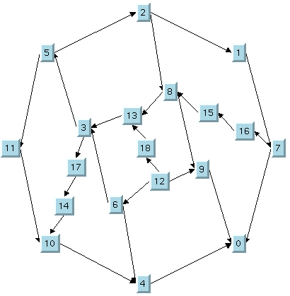
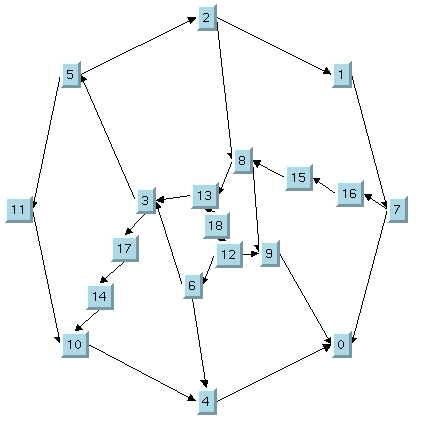
SLOW_GOOD version, which is the default value. Compare the layouts of the same graph in
Node placement algorithm: SLOW_GOOD and
Node placement algorithm: QUICK_BAD to get an idea of the difference between these algorithms.
In CSS, you omit the prefix IlvTopologicalMeshLayout when specifying the value of the nodes placement.
Node placement algorithm: SLOW_GOOD
Node placement algorithm: QUICK_BAD
Outer cycle (TML)
The Topological Optimization step of TML computes a set of cycles that can be used as the outer cycle in the Nodes Placement step. By default, the longest cycle is actually used (that is, the cycle containing the largest number of nodes). However, you may find it useful to try a different outer cycle. To do so in Java, use the method:
void setExteriorCycleId(int cycleId)
The valid values for cycleId range from zero to the number of cycles computed by the Topological Optimization step minus one. This number is returned by the method:
int getNumberOfPossibleExteriorCycles()
If the number is not in this range, the value zero is used.
You can use these methods only after having performed the layout successfully. Otherwise, no outer cycle is defined.
When the layout is performed again with a new outer cycle, only the Nodes Placement step of TML is performed, and not the time-consuming the Topological Optimization step. This is true if the topology of the graph has not been changed (that is, no nodes or links were added or removed), and no parameters that affect the Topological Optimization step have been changed.
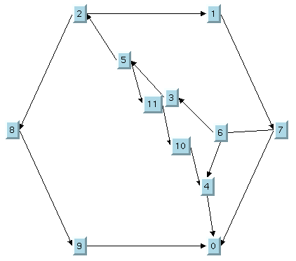
Layout using 1st outer cycle
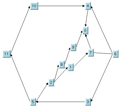
Layout using 2nd outer cycle
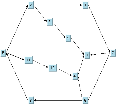
Layout using 3rd outer cycle
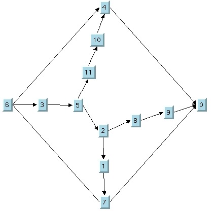
Layout using 4th outer cycle
Refining a graph layout (TML)
After performing the layout on a graph, you may want to improve the quality of the layout by making some manual refinements. The subsequent sections describe several ways to refine your layouts. When the layout is performed again after the refinements have been applied, only the Nodes placement step of TML is redone. The results of the Topological Optimization are reused. This is an important benefit of TML because the algorithm can recompute a layout using new parameters very quickly, without performing the time-consuming Topological Optimization step again.
Using fixed nodes (TML)
One reason for applying manual refinements is to avoid overlapping nodes. To do this, you can use the fixed nodes mechanism. (See
Preserve fixed nodes.)
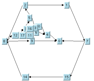
Take a look at the original layout shown in
The original layout with TML. Several overlapping nodes exist in the original layout because the nodes are concentrated in a small region and do not use the available space inside the outer cycle.
The original layout with TML
To correct the problem, you can perform the following steps:
1. 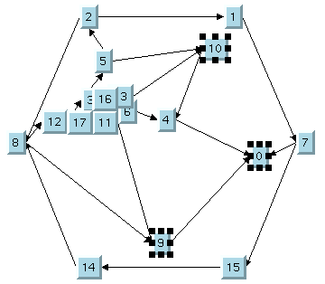
The TML with some nodes moved
2. Specify nodes 0, 9, and 10 as fixed using the
setFixed method.
3. Use the
setPreserveFixedNodes method to specify that the fixed nodes will not be moved when the layout is performed.
4. Perform the layout again. Only Step 2 will be performed.
5. 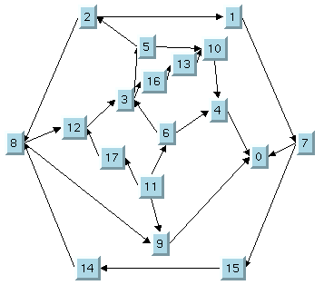
The final TML with some fixed nodes
Using the outer cycle parameter (TML)
By default, the Nodes Placement step of TML produces a layout using the longest outer cycle computed in the Topological Optimization step. (The length of a cycle is the number of nodes that compose the cycle.) Sometimes, a better layout can be obtained using a different choice of the outer cycle. This process of changing the outer cycle parameter and performing the layout again (see
Outer cycle (TML)a) is a manual refinement procedure that can also be used to avoid overlapping nodes.
Note that performing the layout with a new outer cycle requires very little CPU time.
Using the layout region parameter (TML)
Often, overlapping nodes can be avoided by simply increasing the size of the layout region (see
Layout region (TML)).
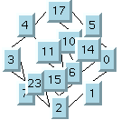
Layout with small layout region and overlapping nodes shows a graph drawing where several nodes overlap because the layout region is too small for the graph.
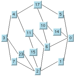
Layout with larger layout region and no overlapping nodes shows the same graph after increasing the size of the layout region. As you can see, now there are no overlapping nodes.
Layout with small layout region and overlapping nodes
Layout with larger layout region and no overlapping nodes
Using a link clipping interface with the TML
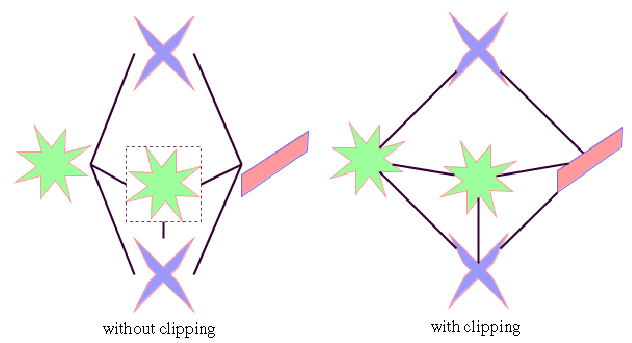
By default, TML does not place the connection points of links. It relies on the link connectors of the nodes to determine the connection points. If no link connectors are installed at the nodes, the default behavior is to connect to a point at the border of the bounding box of the nodes. If the node has a nonrectangular shape such as a triangle, rhombus, or circle, you may want the connection points to be placed exactly on the border of the shape. This can be achieved by specifying a link clip interface. The link clip interface allows you to correct the calculated connection point so that it lies on the border of the shape. The following figure shows an example.
Effect of Link Clipping interface
You can modify the position of the connection points of the links by providing a class that implements the
IlvLinkClipInterface. An example for the implementation of a link clip interface is in
Link clipping. To set a link clip interface.
To set a link clip interface:
In CSS
It is not possible to set the link clip interface. See
Link clipping.
In Java™
Use the method:
void setLinkClipInterface(IlvLinkClipInterface interface)
NOTE The link clip interface requires link connectors at the nodes of an
IlvGrapher that allow connector pins to be placed freely at the node border. It is recommended that you use
IlvFreeLinkConnector or
IlvClippingLinkConnector for link connectors to be used in combination with
IlvGrapher objects. The clip link connector updates the clipped connection points automatically during interactive node movements.
Copyright © 2018, Rogue Wave Software, Inc. All Rights Reserved.
