- java.lang.Object
-
- ilog.views.graphlayout.IlvGraphLayout
-
- ilog.views.graphlayout.bus.IlvBusLayout
-
public class IlvBusLayout
extends IlvGraphLayout
The main class for the Bus Layout algorithm.The Bus Layout algorithm is designed to display bus network topologies, that is, a set of nodes connected to a bus node. The algorithm takes into account the size of the nodes (so that no nodes overlap) and provides several ordering and alignment options.
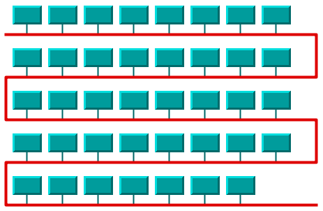
Here is a sample drawing produced with the Bus Layout algorithm:
To use this layout style, you must specify a node of the attached graph model as the "bus" using the method
#setBus. The bus node must be an instance of a class that implements the interfaceIlvPolyPointsInterface, for instance, anIlvPolyline(or a subclass). The layout algorithm gives the bus polyline the appropriate shape by moving, adding, or removing points as needed. Therefore, the initial number of points and the position of those points are not significant. Note that for the bus object, you can use only implementations of the interfaceIlvPolyPointsInterfacefor which the methodsIlvPolyPointsInterface.allowsPointInsertion()andIlvPolyPointsInterface.allowsPointRemoval()returntrue.Only the nodes connected to the bus node by a link are laid out.
The following figure illustrates the dimensional parameters of the layout algorithm.
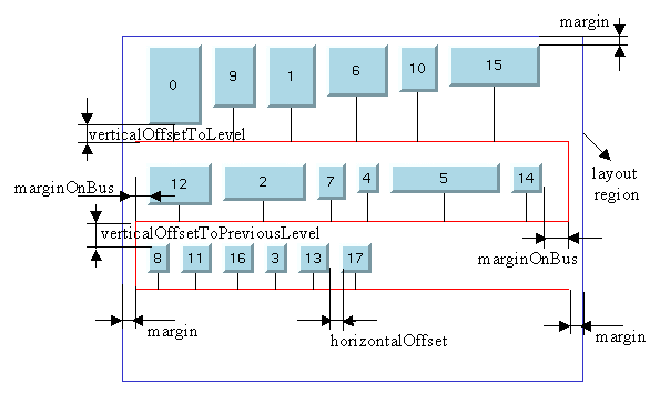
The algorithm not only computes the shape of the bus object and the position of the nodes connected to the bus but also the connection points of the links on the bus node. These points are computed in such a manner as to obtain vertical links.
If the attached graph model encapsulates an
IlvGrapher, the computation of the connection points is provided by a special subclass ofIlvLinkConnectorcalledIlvBusLinkConnector. Otherwise, the method#getConnectionPointis provided to allow you to implement a different mechanism.See the corresponding chapter of the User's Manual for details on the algorithm, the types of graphs for which this algorithm can be used, the features, code samples, parameters, and so on.
Note that the initial position of the nodes (at the moment you start the layout) does not affect the resulting layout. However, nodes specified as fixed are not moved if you call the method
#setPreserveFixedNodeswith atrueargument. The other nodes are placed in such a way that overlaps with the fixed nodes are avoided.
CSS example:
SDM {
     GraphLayout : true;
 }
GraphLayout {
     graphLayout : @#layout;
     // optional settings for the graph layout renderer
 }
Subobject#layout {

     class : "ilog.views.graphlayout.bus.IlvBusLayout";

     allowedTime : "3";

     busLineExtremityAdjustingEnabled : "false";

     busWidthAdjustingEnabled : "false";

     coordinatesMode : "MANAGER_COORDINATES";

     flowDirection : "LEFT_TO_RIGHT";

     globalVerticalAlignment : "CENTER";

     horizontalOffset : "3.0";

     incrementalMode : "false";

     layoutOfConnectedComponentsEnabled : "false";

     linkStyle : "STRAIGHT_LINE_STYLE";

     margin : "3.0";

     marginOnBus : "3.0";

     maxNumberOfNodesPerLevel : "2";

     minBusyTime : "3";

     nodeComparator : "@#nodeComparator";

     nodePosition : "NODES_ABOVE_BUS";

     verticalOffsetToLevel : "3.0";

     verticalOffsetToPreviousLevel : "3.0";

 }
Subobject#nodeComparator {
    class : "ilog.views.sdm.renderer.graphlayout.IlvSDMObjectComparator";
    textualSortCriteria : "data,name,ascendent;data,value,descendent;comparator,DESCENDING_HEIGHT,ascending";
}
CSS specification of per-node and per-link layout parameters:The following table lists the per-object rendering properties of the
GraphLayoutrenderer:PropertyTypeDefaultDescriptionGraphLayoutIlvGraphLayoutnullLets you define a different graph layout algorithm for each subgraph. If one is not specified, the same algorithm is applied recursively to all subgraphs.LayoutFixedStringfalseDeprecated, replaced by Fixed.FixedStringfalseLets you specify that the node or link must not be moved or reshaped by the layout algorithm.LayoutGroupStringnullLets you apply the algorithm to different groups of objects, one group after the other.LayoutIgnoredbooleanfalseIftrue, the object is ignored by the layout.The per-node and per-link layout parameters are specified in the style sheet through the CSS rules for nodes and links, not through the CSS rule for graph layout. For instance:
link.tag {
      LinkStyle : "ORTHOGONAL_STYLE";
 }
Note that the names of the node and link layout parameters use an initial capital, unlike the regular properties. See also the documentation of the class IlvGraphLayoutRenderer.
-
-
Property Summary
Properties Modifier and Type Property and Description longallowedTime
Sets the upper limit for the duration of the layout algorithm.booleanbusLineExtremityAdjustingEnabled
Enables adjustment of the extremity points of the bus line.booleanbusWidthAdjustingEnabled
Enables adjustment of the bus width to the total width of the nodes.java.lang.Stringclass
Default constructor.intcoordinatesMode
Sets the coordinates mode to be used during layout.intflowDirection
Allows you to specify the flow direction of the nodes.intglobalVerticalAlignment
Sets the global vertical alignment style.doublehorizontalOffset
Sets the horizontal offset between nodes placed on the same level of the bus.booleanincrementalMode
Enables or disables the incremental mode.booleanlayoutOfConnectedComponentsEnabled
Sets whether the generic connected component layout mechanism is enabled.intlinkStyle
Sets the style of the shape of the links.doublemargin
Sets the horizontal offset between the left/right border of the bus level and the left/right border of the layout region.doublemarginOnBus
Sets the horizontal offset between the first/last node on a given level and the left/right margin of the level.intmaxNumberOfNodesPerLevel
Sets the maximum number of nodes per level.longminBusyTime
Sets the minimal time that the layout algorithm can be busy.java.util.ComparatornodeComparator
Sets the comparator used for sorting the nodes.intnodePosition
Sets the position of the nodes with respect to the bus line.doubleverticalOffsetToLevel
Sets the vertical offset between the nodes and the horizontal level of the bus to which they are connected.doubleverticalOffsetToPreviousLevel
Sets the vertical offset between the nodes and the horizontal level of the bus above the nodes.
-
-
-
Property Detail
-
class
public java.lang.String class
Default constructor.
CSS example:class : "ilog.views.graphlayout.bus.IlvBusLayout";
-
allowedTime
public long allowedTime
Sets the upper limit for the duration of the layout algorithm.When an iterative layout algorithm is used, the iterations can be stopped when this time is exceeded. Noniterative algorithms can also use this parameter as an upper limit for the computation time. The default value is normally
32000(32 seconds). Subclasses that support this feature can use a different default value depending on their particular behavior. Layout algorithms that are stopped in this way set the result code of the layout report either toIlvGraphLayoutReport#STOPPED_AND_VALIDor toIlvGraphLayoutReport#STOPPED_AND_INVALID.When the connected components of disconnected graphs are laid out separately (see
#supportsLayoutOfConnectedComponents()), the specified allowed time is considered as the total time for the layout of all the connected components plus the time for the connected components layout.Note that the layout algorithm may not obey exactly the allowed time specification.
Note for implementers of layout algorithms: the method
#performLayout(boolean, boolean, boolean)does NOT automatically stop the layout when the allowed time is exceeded. It is the sole responsibility of the implementation of the method#layout(boolean)to do this.A
RuntimeExceptionis thrown if the layout does not support this mechanism.
CSS example:allowedTime : "3";
-
busLineExtremityAdjustingEnabled
public boolean busLineExtremityAdjustingEnabled
Enables adjustment of the extremity points of the bus line.If adjustment is enabled, the extremity points of the bus line are adjusted, if necessary, to the total width of the nodes, plus the margins. This can make a difference when there is only one horizontal bus line, or when the flow direction is
#ALTERNATE.If adjustment is disabled, the horizontal lines of the bus have equal length.
The default value is
false.
CSS example:busLineExtremityAdjustingEnabled : "false";
-
busWidthAdjustingEnabled
public boolean busWidthAdjustingEnabled
Enables adjustment of the bus width to the total width of the nodes.If adjustment is disabled, the width of the bus object, that is, the difference between the maximum and minimum x-coordinates, depends on the current width of the layout region. If adjustment is enabled, the width of the bus object is automatically adjusted to the total width of the nodes, plus the margins.
The parameter has no effect if
#getFlowDirection()returns#ALTERNATE.Bus width adjustment is disabled by default.
CSS example:busWidthAdjustingEnabled : "false";
-
coordinatesMode
public int coordinatesMode
Sets the coordinates mode to be used during layout.Valid values are:
-
ilog.views.graphlayout.IlvGraphLayout#MANAGER_COORDINATES- The geometry of the graph is computed using the coordinate space of the manager (that is, the attachedIlvGrapher) without applying any transformation.This mode should be used if you visualize the graph at zoom level 1, or you do not visualize it at all, or the graph contains only fully zoomable objects. In all these cases there is no need to take the transformer into account during the layout.
Note that in this mode the dimensional parameters of the layout algorithms are considered as being specified in manager coordinates.
-
ilog.views.graphlayout.IlvGraphLayout#VIEW_COORDINATES- The geometry of the graph is computed in the coordinate space of the manager view. More exactly, all the coordinates are transformed using the current reference transformer.This mode should be used if you want the dimensional parameters of the layout algorithms to be considered as being specified in manager view coordinates.
-
ilog.views.graphlayout.IlvGraphLayout#INVERSE_VIEW_COORDINATES- The geometry of the graph is computed using the coordinate space of the manager view and then applying the inverse transformation. This mode is equivalent to the "manager coordinates" mode if the geometry of the graphic objects strictly obeys the transformer. (A small difference may exist because of the limited precision of the computations.)On the contrary, if some graphic objects are either nonzoomable (see
IlvGraphic#zoomable) or semizoomable (for example, links with a maximum line width), this mode gives different results than the manager coordinates mode. These results are optimal if the graph is visualized using the same transformer as the one taken into account during the layout.Note that in this mode the dimensional parameters of the layout algorithms are considered as being specified in manager coordinates.
The default value is
IlvGraphLayout#INVERSE_VIEW_COORDINATES.This option is useful only if the attached graph model is an
IlvGrapherAdapter(or a subclass). Otherwise, it has no effect. Note: the coordinates mode of the layout is used only while this layout is running. If layout is not running, operations on the grapher adapter use the coordinates mode that was set on the grapher adapter directly (seeIlvGrapherAdapter#setCoordinatesMode).
CSS example:coordinatesMode : "MANAGER_COORDINATES";
Allowed values: MANAGER_COORDINATESVIEW_COORDINATESINVERSE_VIEW_COORDINATES -
-
flowDirection
public int flowDirection
Allows you to specify the flow direction of the nodes.-
#LEFT_TO_RIGHT- The nodes "flow" from left to right on all the levels of the bus. -
#ALTERNATE- The nodes "flow" from left to right on the odd bus levels (first, third, fifth, and so on) and from right to left on the even bus levels (second, fourth, sixth, and so on). The levels are numbered from the top.
The default is
LEFT_TO_RIGHT.
CSS example:flowDirection : "LEFT_TO_RIGHT";
Allowed values: LEFT_TO_RIGHTALTERNATE -
-
globalVerticalAlignment
public int globalVerticalAlignment
Sets the global vertical alignment style. It controls the vertical alignment of nodes inside the level where they are placed.Valid values are:
-
#CENTER- the node is centered on its level. -
#TOP- the node is aligned with the top border of the level. -
#BOTTOM- the node is aligned with the bottom border of the level. -
#MIXED- each node can have a different alignment option. In this case, the vertical alignment of each individual node can be set by the method#setVerticalAlignment(Object, int), so that different alignments can occur in the same layout.
The default value is
#TOP.
CSS example:globalVerticalAlignment : "CENTER";
Allowed values: CENTERTOPBOTTOMMIXED -
-
horizontalOffset
public double horizontalOffset
Sets the horizontal offset between nodes placed on the same level of the bus.
CSS example:horizontalOffset : "3.0";
-
incrementalMode
public boolean incrementalMode
Enables or disables the incremental mode.If the incremental mode is enabled, the stability of the layout is preserved as much as possible when new nodes are added, existing ones removed, or node sizes modified. This means that the nodes are placed at the same location or in the same order as in the previous layout whenever it is possible. In this mode, the layout algorithm processes the changes incrementally rather than redoing the entire layout for every change.
To preserve the stability, the incremental mode can keep some regions free. Therefore, the total area of the layout can be larger than in nonincremental mode.
Note that the layout is redone from scratch after a change of one of the following parameters:
- layout region
- horizontal offset parameters
- maximum number of nodes per level
The default value is
false(disabled).
CSS example:incrementalMode : "false";
-
layoutOfConnectedComponentsEnabled
public boolean layoutOfConnectedComponentsEnabled
Sets whether the generic connected component layout mechanism is enabled. If enabled on a layout class that supports this mechanism (see#supportsLayoutOfConnectedComponents()), the method#performLayout(boolean, boolean, boolean)cuts the attached graph model into connected components and lays out each connected component separately. Then the connected components are placed using the layout instance returned by the method#getLayoutOfConnectedComponents().Notice that the connected component layout is not used if the graph is connected.
A
RuntimeExceptionis thrown if the layout does not support this mechanism.The default value is the value returned by the method
#isLayoutOfConnectedComponentsEnabledByDefault().
CSS example:layoutOfConnectedComponentsEnabled : "false";
-
linkStyle
public int linkStyle
Sets the style of the shape of the links. Valid values are#STRAIGHT_LINE_STYLE(the links are given a straight-line shape) and#NO_RESHAPE_STYLE(no reshape is performed on the links).This feature can be useful when the graph contains links that have intermediate points and are not straight-line links (for instance,
IlvPolylineLinkImagelinks with intermediate points).The default value is
#STRAIGHT_LINE_STYLE.Note that when the graph attached to the layout is of type
IlvGrapher, the effect of the link reshaping depends on the type of the links and the connectors installed at the node. For#STRAIGHT_LINE_STYLE, we recommend using links of typeIlvPolylineLinkImageand attaching a link connector of typeIlvBusLinkConnectoron the bus node (if no link connector is attached, the layout automatically attaches it). Other link or connector types may cause anIlvInappropriateLinkExceptionduring layout. You can use the methodIlvGraphLayoutUtil#EnsureAppropriateLinksbefore layout or when the exception is caught to convert all links and link connectors to an appropriate type.
CSS example:linkStyle : "STRAIGHT_LINE_STYLE";
Allowed values: STRAIGHT_LINE_STYLEStraight-line links NO_RESHAPE_STYLENo link reshape
-
margin
public double margin
Sets the horizontal offset between the left/right border of the bus level and the left/right border of the layout region.Note that the following relationship must be respected:
getCalcLayoutRegion().width > 2*getMargin() +
  2*getMarginOnBus()
CSS example:margin : "3.0";
-
marginOnBus
public double marginOnBus
Sets the horizontal offset between the first/last node on a given level and the left/right margin of the level.
CSS example:marginOnBus : "3.0";
-
maxNumberOfNodesPerLevel
public int maxNumberOfNodesPerLevel
Sets the maximum number of nodes per level. The layout places as many nodes on each level as possible given the size of the nodes, the dimensional parameters (layout region and margins) and the specified maximum number of nodes per level.The minimum value is
1. The default value isInteger.MAX_VALUE, that is, the number of nodes placed in each level is bounded only by the size of the nodes and the dimensional parameters.
CSS example:maxNumberOfNodesPerLevel : "2";
-
minBusyTime
public long minBusyTime
Sets the minimal time that the layout algorithm can be busy. This is the time between two calls of#layoutStepPerformed()when the method#callLayoutStepPerformedIfNeeded()is used.The objective is to avoid the overhead of
#layoutStepPerformed()becoming too high if the method is called too often. Internal routines of layout algorithms usually call#callLayoutStepPerformedIfNeeded(), which calls#layoutStepPerformed()if the time since the last call was at least the minimal busy time.The default value is 50 (milliseconds).
CSS example:minBusyTime : "3";
-
nodeComparator
public java.util.Comparator nodeComparator
Sets the comparator used for sorting the nodes.-
#DESCENDING_HEIGHT- The nodes are ordered in descending order of height. -
#ASCENDING_HEIGHT- The nodes are ordered in ascending order of height. -
#DESCENDING_WIDTH- The nodes are ordered in descending order of width. -
#ASCENDING_WIDTH- The nodes are ordered in ascending order of width. -
#DESCENDING_AREA- The nodes are ordered in descending order of area. -
#ASCENDING_AREA- The nodes are ordered in ascending order of area. -
#ASCENDING_INDEX- The nodes are ordered in ascending order of index value (see#setIndex). -
#DESCENDING_INDEX- The nodes are ordered in descending order of index value (see#setIndex). -
null- The nodes are ordered in an arbitrary way. - Any other implementation of the
Comparatorinterface: the nodes are ordered according to this custom comparator.
null.The ordering of the nodes starts at the upper-left corner of the bus.
In incremental mode (see
#setIncrementalMode) or when nodes are fixed (see#setFixed), the order of the nodes is not guaranteed to obey the comparator, since this specification competes with the other constraints.
CSS example:
nodeComparator : "@#nodeComparator";
Subobject#nodeComparator {
    class : "ilog.views.sdm.renderer.graphlayout.IlvSDMObjectComparator";
    textualSortCriteria : "data,name,ascendent;data,value,descendent;comparator,DESCENDING_HEIGHT,ascending";
}
See also the documentation of the class IlvSDMObjectComparator.
-
-
nodePosition
public int nodePosition
Sets the position of the nodes with respect to the bus line.Valid values are:
-
#NODES_ABOVE_BUS- the nodes are placed above the bus line -
#NODES_BELOW_BUS- the nodes are placed below the bus line
The default value is
#NODES_ABOVE_BUS.
CSS example:nodePosition : "NODES_ABOVE_BUS";
Allowed values: NODES_ABOVE_BUSNodes above bus line NODES_BELOW_BUSNodes below bus line -
-
verticalOffsetToLevel
public double verticalOffsetToLevel
Sets the vertical offset between the nodes and the horizontal level of the bus to which they are connected.
CSS example:verticalOffsetToLevel : "3.0";
-
verticalOffsetToPreviousLevel
public double verticalOffsetToPreviousLevel
Sets the vertical offset between the nodes and the horizontal level of the bus above the nodes.
CSS example:verticalOffsetToPreviousLevel : "3.0";
-
-