This section explains how to style nodes as composite graphics by
building a composite graphic directly in the style
sheet.
If you follow the steps given in this
section, you will obtain the composite graphic shown in the
following figure.
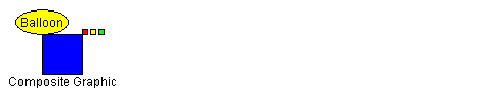
The example composite graphic
Note that this composite graphic itself
contains composite graphics.
This composite graphic will be used to represent nodes of a
specific user-defined type.
The data to be displayed comes from the XML
file shown in the following code example.
The example XML data file
<?xml version="1.0" encoding="UTF-8"?>
<SDM>
  <MyNode >
    <property name="x">100</property>
    <property name="y">100</property>
    <property name="label">Composite Graphic</property>
    <property name="alarm">Balloon</property>
  </MyNode>
</SDM>
There is just one node
defined, with user-defined type
MyNode
.
The x and y properties give the location of
the node.
Each of the other properties will be styled
as a child of a composite graphic.
To build composite nodes in CSS:
-
Enable Composite GraphicsTo make use of composite graphics in the style sheet, enable the Composite Graphics capability in the SDM rule, as follows:
SDM { Composite:true; } -
Customize some objects as composite graphicsAdd rules to customize objects with the user-defined type
MyNodeas composite graphics, as follows:node.MyNode { class:'ilog.views.sdm.graphic.IlvSDMCompositeNode'; children[0]:@+Rectangle; } Subobject#Rectangle { class:'ilog.views.graphic.IlvRectangle'; width:40; height:40; fillOn:true; background:blue; }A composite graphic in Rogue Wave® JViews Diagrammer is an instance of the class IlvSDMCompositeNode. It always has at least one child element. This first child has index 0 in thechildrenarray. In this example, the first child is created as an IlvRectangle object. It is defined with the IDRectanglein a separate rule.At this stage, theMyNodenode would be displayed by the SDM engine as shown in the following figure. A composite node with only the first child element
 -
Add a decorated childTo display the label attribute of the
MyNodeobject, add another child element to theMyNoderule as shown in the following code example.node.MyNode { class:'ilog.views.sdm.graphic.IlvSDMCompositeNode'; layout:@+AttachmentLayout; children[0]:@+Rectangle; children[1]:@+Label; constraints[1]:@=attachmentLabel; } ... Subobject#AttachmentLayout { class:'ilog.views.graphic.composite.layout.IlvAttachmentLayout'; } Subobject#Label { class:'ilog.views.graphic.IlvText'; label:@label; } Subobject#attachmentLabel { class:'ilog.views.graphic.composite.layout.IlvAttachmentConstraint'; hotSpot:TopCenter; anchor:BottomCenter; }This second child has index 1 in thechildrenarray. In this example, the second child is created as an IlvText object. It is defined with the IDLabelin a separate rule.Once there is a further child, you need to specify which layout to use. In this case, the Attachment Layout is appropriate because it is the most general. You also need to add a constraint to specify how the second child is attached to the first. The index of theconstraintsarray must correspond to the index of thechildrenarray.For an Attachment Constraint, you must specify the following properties in a separate rule:hotSpot, which is the point on the subsequent child object by which it is attachedanchor, which is the point on the first child to which the subsequent child is attached
At this stage, theMyNodenode would be displayed by the SDM engine as shown in figure A composite node with only the first child element.Note that an Attachment can be shared and so the CSS construct@=is used in theMyNoderule. Child graphics cannot be shared and so they are created with the CSS construct@+.WarningYou must NOT use the @# construct to define composite graphics. Only the @+ and @= constructs are allowed. Using @# may lead to a wrong or inconsistent layout. A composite node with two child elementsThe top center of the second child ( IlvText object) is anchored to the bottom center of the first child ( IlvRectangle object).The Attachment Layout provides nine possible attachment locations, as shown in the following figure.
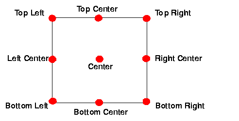 Possible attachment locations
 -
Add an Aligned Nested Composite GraphicTo add the three little rectangles at the upper right corner of the blue rectangle, you need to add a child which is itself a composite graphic.First define the three rectangles with IDs
Rect1,Rect2, andRect3, as shown in the following code example. These are the simple graphic objects which make up the nested composite graphic.Subobject#Rect1 { class:'ilog.views.graphic.IlvRectangle'; width:5; height:5; background:red; fillOn:true; } Subobject#Rect2 { class:'ilog.views.graphic.IlvRectangle'; width:5; height:5; background:yellow; fillOn:true; } Subobject#Rect3 { class:'ilog.views.graphic.IlvRectangle'; width:5; height:5; background:green; fillOn:true; }Next add another child element to theMyNoderule as shown in the following code example.node.MyNode { ... children[2]:@+Rectangles; ... constraints[2]:@=attachmentRectangles; } ... Subobject#Rectangles { class:'ilog.views.sdm.graphic.IlvSDMCompositeNode'; layout:@+StackerLayout; children[0]:@+Rect1; children[1]:@+Rect2; children[2]:@+Rect3; } Subobject#attachmentRectangles { class : "ilog.views.graphic.composite.layout.IlvAttachmentConstraint" ; hotSpot:BottomLeft; anchor:TopRight; } Subobject#StackerLayout { class:'ilog.views.graphic.composite.layout.IlvStackerLayout'; }This third child has index 2 in thechildrenarray. It is composite graphic, that is, an IlvSDMCompositeNode. object and it is defined with the IDRectanglesin a separate rule.In theSubobject#Rectanglesrule, you need to specify which layout to use for the three children. In this case, the Stacker Layout is appropriate because a Stacker Layout is used to align graphics, either horizontally or vertically. The graphics to be aligned horizontally in this example are the children of the composite node.You also need to add a constraint to theMyNoderule to specify how the third child is attached to the first. In this example, the bottom left of the third child (IlvSDMCompositeNodeobject) is anchored to the upper right of the first child (IlvRectangleobject).At this stage, theMyNodenode would be displayed by the SDM engine as shown in the following figure. A composite node with three child elements, one a composite
 -
Add a Centered Nested Composite GraphicFinally, add an information balloon to display the
alarmattribute.To add the information balloon with its text, you need to add another child which is itself a composite graphic.First define the ellipse shape and the label with IDsEllipse, andBalloonLabel, as shown in the following code example. These are the simple graphic objects which make up the nested composite graphic.Subobject#Ellipse { class:'ilog.views.graphic.IlvEllipse'; background:yellow; fillOn:true; } Subobject#BalloonLabel { class:'ilog.views.graphic.IlvText'; label:@alarm; }Next add another child element to theMyNoderule as shown in the following code example.node.MyNode { ... children[3]:@+Balloon; ... constraints[3]:@=attachmentBalloon; } ... Subobject#Balloon { class:'ilog.views.sdm.graphic.IlvSDMCompositeNode'; layout:@+CenteredLayout; children[0]:@+Ellipse; children[1]:@+BalloonLabel; } Subobject#CenteredLayout { class:'ilog.views.graphic.composite.layout.IlvCenteredLayout'; insets:5,5,5,5; } Subobject#attachmentBalloon { class:'ilog.views.graphic.composite.layout.IlvAttachmentConstraint'; hotSpot:BottomCenter; anchor:TopLeft; }This fourth child has index 3 in thechildrenarray. It is a composite graphic, that is, an IlvSDMCompositeNode. object and it is defined with the IDBalloonin a separate rule.In theSubobject#Balloonrule, you need to specify which layout to use for the two children. In this case, the Centered Layout is appropriate because a Centered Layout is used to center one graphic on another. A Centered Layout displays an outer graphic (the child at index 0) around an inner graphic (the child at index 1). The fourinsetsspecify the pixel distances from each edge of the bounding box of the outer graphic. Note that the two child objects maintain their relative position when the composite graphic is resized.You also need to add a constraint to theMyNoderule to specify how the fourth child is attached to the first. In this example, the bottom center of the fourth child (IlvSDMCompositeNodeobject) is anchored to the upper left of the first child (IlvRectangleobject).At this stage, theMyNodenode would be displayed by the SDM engine as shown in figure The example composite graphic, as required.