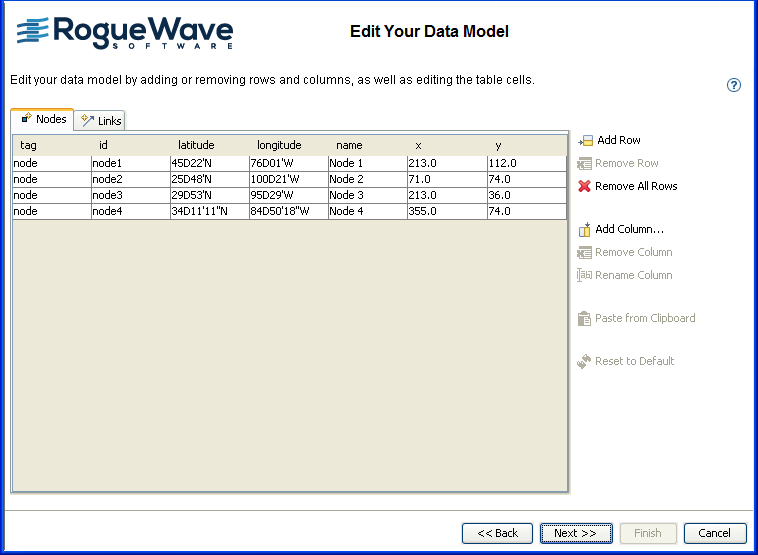
You can edit the basic data model in the
following ways:
- Add and remove rows (a row represents an object in the data model)
- Add, remove, and rename columns (a column represents a property of the objects in the data model)
- Change cell values (a cell represents a property of a specific object)
- Remove all objects
- Restore the data model to its initial state
- Paste data from the clipboard
For example, you could remove the x and y
columns if you do not want an X/Y Diagram. You can create a Layout
Diagram without any specific layout attributes.
To delete all the data values, click Remove
All Rows. To retrieve the values you saw initially, click Reset to Default.
Properties id, tag,
from and to
are mandatory for the SDM model and therefore cannot be removed or
renamed by the user.
Paste from Clipboard replaces the
contents of the current table by the information present in the
clipboard. It asks whether you want the column names to be named
based on the first row. If so, the first line of data is used to
give the column names. If not, the column names are named as A, B,
C, and so on, and you can rename them later.
Editing the in-memory data model
To create a simple network model:
-
Click each
namevalue. -
Rename the nodes to Paris, MountainView, Frankfurt, and Singapore.
-
Click Add Column.
-
Add a column called
status, one calledminor, and one calledmajor.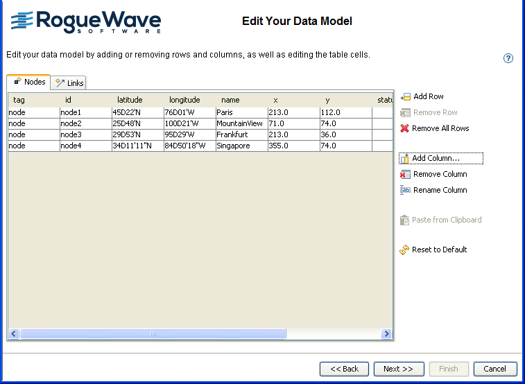 A simple network model in memory
 -
Click in the new columns to enter the data values as shown in the following table.
status minor major Paris Available 2 0 Mountain View Unavailable 4 2 Frankfurt Available 0 0 Singapore Available 0 1 -
Click Next to select the type of diagram.
-
Select the X/Y Diagram option.
-
Click Finish to exit the wizard.
-
Click File > Save As and save the network diagram as network.idpr.
-
Keep this diagram open to use in the next section.
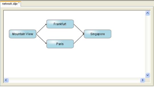
The initial network diagram