In Diagram Editing mode you can insert nodes and links into a
diagram and then position them. You can drag objects to new
positions and change the way they are interconnected. When you
update the diagram manually in this mode, the data
model is automatically updated to remain synchronized with your
diagram. For example, the data model changes to reflect new
positions if you have a Map Diagram or an X/Y Diagram; the data
model changes to reflect differences in interconnections.
In Diagram Editing mode, you cannot change
the style rules nor see all application behavior.
To enter Diagram Editing mode:
-
Click the Diagram Editing button in the vertical toolbar.
Panes in Diagram Editing mode
In Diagram Editing mode, the panes of
the Designer window are as follows:
- Upper left: Data Model tree, showing the model objects displayed
- Right: Diagram in Diagram Editing mode
- Lower left: Data Properties of the selected object, showing the current values.
Selection in Diagram Editing mode
If you select objects in the tree or the
diagram, they are displayed in the diagram according to the
style rules you have defined that govern selection (if any).
For example, if you have specified in a rule that a certain
type of object should change color when selected by a user of
your application, you will see this result when you select an
object of that type. If you right-click an object, you can
switch the selected/deselected state of the object.
Diagram and data model modification
You can select a type of node from the right end of the
horizontal toolbar and drop it onto the diagram. You can select
a type of link and click its source node and destination node
to create a link. Effectively, you add objects to your data model when you drop them onto the
diagram.
Some data models are not editable, for
example, data models derived from JDBC data sources. You cannot
edit the diagram in this case.
The following figure shows a flow diagram. This example is
available as project file
flow.idpr.
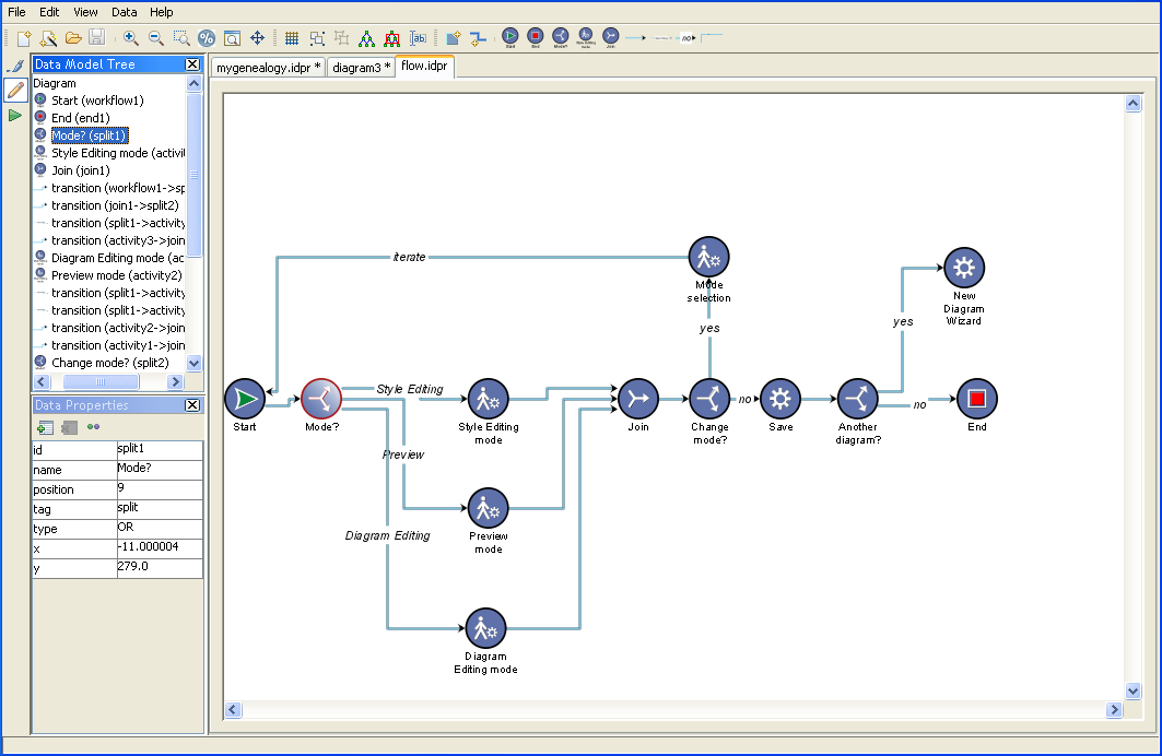
The flow diagram developed in Diagram
Editing mode
To add a node:
-
Click the node icon in the horizontal toolbar.
-
Click anywhere in the diagram.
For example, to add a manual activity, click the manual activity
icon  in the
toolbar and then click below the existing manual activities in
the flow diagram.
in the
toolbar and then click below the existing manual activities in
the flow diagram.
in the
toolbar and then click below the existing manual activities in
the flow diagram.
In addition to the nodes available from
the toolbar, you can create new types of node.
To create a new type of node:
-
Click the Create New Type of Node icon
 in the
toolbar.
in the
toolbar.
-
Enter the type of the new node in the dialog.
-
Click OK.
The style of the new node is defined by the type set for the
node. If no rule has been set for this node type, then the rule
“
node
” applies alone.
To move a node:
-
Click the node and drag it to a new position.Any links attached to the node remain attached.
-
If it is useful, you can perform a layout on all the nodes or a selected subset of them, according to the layout algorithm currently configured in the style sheet.
To add a link:
-
Click the link icon in the horizontal toolbar.
-
Click one node in the diagram (source node).
-
Click another node (destination node).
For example, in the flow diagram, click
the good link icon in the toolbar, then click the Mode? node and
then click the new manual activity node.
In addition to the links available from
the toolbar, you can create new types of link.
To create a new type of link:
-
Click the icon
 in the
toolbar.
in the
toolbar.
-
Enter the type of the new link in the dialog.
-
Click OK.
The style of the new link is defined by the type set for the
link. If no rule has been set for this link type, then the rule
“
link
” applies alone.
To move a link:
-
Click the end you want to detach and drag it to a different node.The other end of the link remains attached as before.If you perform a layout on all the nodes or a selected subset of them, affected links will change their routes.
To add a user-defined type:
-
Select a node.
-
Click the Set User-Defined Type button in the Data Properties toolbar.
-
Enter new values for the properties of the user-defined type.
Note that the
tag
property remains fixed and, instead, your user-defined type is
identified by the value of the
CSSclass
property.
If you switch back to Style Editing mode and create a style rule
specifying the appropriate
tag
value and
CSSclass
value, you can select a different icon in the Styling Customizer
to represent the new user-defined type.
When you add a user-defined type, its
icon is added to the horizontal toolbar in Diagram Editing mode
automatically.
To add a new property to a type of node
or link:
-
Click the New Property button in the Data Properties toolbar.
-
Enter the name and value of the new property.
To remove a property of a type of node
or link:
-
Select the property in the Data Properties pane.
-
Click the Delete Property button in the Data Properties toolbar.