JViews Diagrammer uses
cascading style sheets as a powerful tool to create and
customize graphic objects that represent the objects in your data
model.
When you start a diagram through the wizard
and load data from an XML file, default styling is applied.
The default theme gives a plain appearance and does not show all
the data, see figure Initial diagram and graph layout customizer.
You can change this behavior by defining your own style
rules.
The graph layout used is Hierarchical, from
left to right. This is governed by the Graph Layout option in the
Options section of the Style Rules. To see the Styling Customizer,
select Graph Layout; see the following figure.
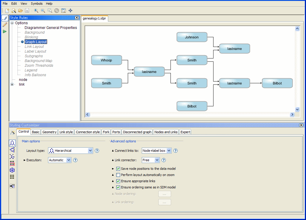
Initial diagram and graph layout
customizer
You can see all the default style rules in a
tree structure. You can add a new rule, modify an existing rule,
delete an existing rule, and change the priority of a rule (its
level in the list) by using the Rule menu which is available when
you right-click a rule in the tree.
Selecting the rule on all nodes
There is one rule defined for all nodes in the diagram. This rule
sets the default shape, size, coloring, and label of all nodes.
When you select the
node
entry in the Style Rules, all nodes to which this general rule
applies are selected in the diagram and you can see their
properties in the Styling Customizer, as shown in the following
figure.
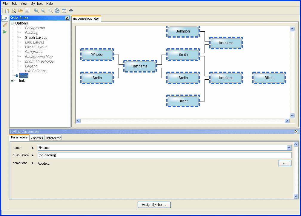
Selecting the node rule
The nodes in the diagram are represented
by symbols.
Note the icon next to the
node
rule; it indicates that the rule applies to the selected objects.
Sometimes there is more than one icon displayed, see Rule-select and blue icons.
The most general rule (
node
) applies to all nodes. Other node rules are more specific than
this one.
In Style Rules, you can set a rule on nodes in general by
selecting
node.
There can be only one rule at the top level, that is, one
node
rule and one
link
rule. If you try to create a second
node
rule or
link
rule, you are prompted to delete the existing one. You can think
of these general rules as setting default property values for all
nodes and all links.
The data model specified in the XML file contains nodes and links
of the following user-defined types:
person
,
couple
,
couplelink
, and
childlink
. These types are the top-level elements in the XML file. You can
set a rule on any nonlink top-level element in the XML file by
selecting
node
and then specifying a valid user-defined type, for example,
node.person
. See Customizing genealogy nodes by type to
learn how to apply specific rules to nodes.
Selecting the rule on all links
There is one rule defined for all links in the diagram. This rule
sets the default line width, coloring, and arrowhead (if any) of
all links. When you select the
link
entry in the Style Rules, all links to which this general rule
applies are selected in the diagram, and the properties set are
displayed in the Styling Customizer, see the following figure.
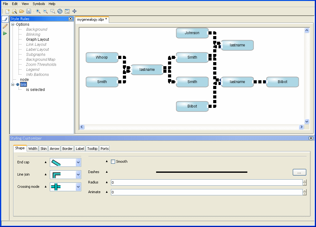
Selecting the link rule
The links in the diagram are represented
by a general link object, which is customized in terms of its
Shape and Skin (content), and optional Arrow, Border, and Label.
The
link
rule has an icon next to it because it applies to the selected
objects (all the links).
In the Style Rules, you can set a rule on links in general by
selecting
link
.
The data model specified in the XML file contains nodes and links
of the following user-defined types:
person
,
couple
,
couplelink
, and
childlink
. These types are the top-level elements in the XML file. You can
set a rule on any link element in the XML file by selecting
link
and then specifying a valid type of link, for example,
link.childlink
. See Customizing genealogy links by type to
learn how to apply specific rules to links.