Linking symbols
Describes the linking mechanism in a dashboard diagram.

Explains how to link two symbols in a dashboard diagram.
Describes how you can specify the exact connection points of the links on a symbol.
Explains how to apply an automatic link layout in a dashboard diagram.
Adding links
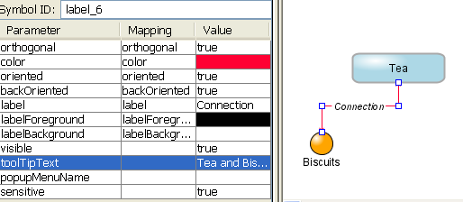
A link is a special type of symbol used to connect two standard symbols. You can customize the shape, color, visibility, orientation, and associated text and pop-up menus for labeled links. For less sophisticated links, such as the Simple Link or the Colored Link, you can change a limited number of these parameters.
Link parameters
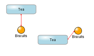
To link two symbols in a dashboard diagram:
1. Select a link from the Links tab in the Palettes pane.
2. Drag the link from the Palettes pane to the first symbol you want to connect.
3. Click the second symbol.
4. 
Adding a link between two symbols
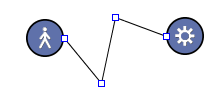
To add intermediate points on the link:
1. Select the link.
2. Press the Control key.
3. Click the link to add new points.
You can then move the link points inside the diagram.
Adding intermediate points to a link
To remove intermediate points on a link:
1. Press the Control key.
2. Click the intermediate point you want to remove.
Link-in and link-out ports
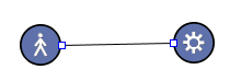
By default, as a symbol moves in a dashboard diagram, the link between two symbols connects to the closest ports.
Standard links attach to the closest port on a symbol
A palette symbol can be designed with elements that can be used as link-in or link-out ports. Links connected to link-in and link-out ports stay bound to these ports as the different symbols move.
Instead of connecting a link to the base shape of a symbol, you can connect it to a specific element of the symbol defined as a link port. It is in the Symbol Editor that you can define a symbol element as an in port, an out port, or an in and out port. See
Using link-in and link-out ports in
Using the Symbol Editor in
Developing with Design Tools for more information.
When you choose the source symbol of a link, if the mouse pointer is on a link-out port, this symbol element is highlighted. When you choose the target symbol of a link, if the mouse pointer is on a link-in port, this symbol element is highlighted.
Enabling link layout
The Dashboard Editor allows you to perform an automatic link layout of your dashboard diagram.
To perform an automatic link layout:
Click
Options > Link Layout Enabled in the menu bar.
A check mark appears in front of the menu item to indicate that the layout is enabled.
The intermediate points of your links, if any, are replaced by the points computed by the JViews link layout. As long as the option is enabled, the links are automatically adjusted when you move a node in the dashboard diagram.
If you disable the link layout, the intermediate points of your links remain fixed unless you explicitly move them.
The Link Layout Enabled option is saved with the dashboard file. If you open a file in which the option is enabled, the link layout is automatically activated.
If you do not need to move your symbols at run time, you can disable the Link Layout Enabled option before saving the file.
For more information about the link layout, see Link Layout (LL) in the Using Graph Layout Algorithms user’s documentation.
Copyright © 2018, Rogue Wave Software, Inc. All Rights Reserved.