Creating a user-defined data model
Explains how to create a simple network model based on the in-memory data in the New Diagram Wizard.

Explains how to create a user-defined data model from the New Diagram wizard.
Explains how to edit the default user-defined data model to create a network model.
Explains how to customize the default representation of nodes.
Creating the data model
The user-defined data model allows you to start from in-memory data in Java™ classes compliant with the data model requirements of JViews Diagrammer.
To create a data model in memory interactively:
1. Click File > New from Wizard.
2. Select the user-defined data model option (default option) and click Next.
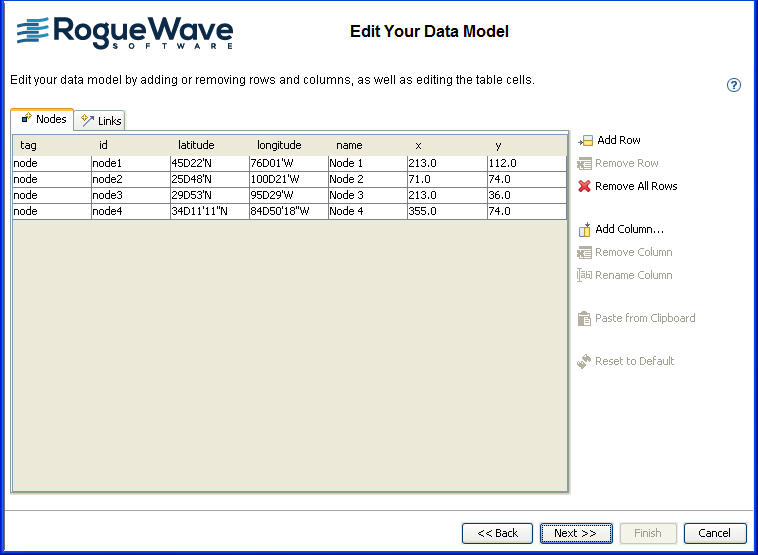
You start from a basic data model containing four nodes and four links, see
Editing the in-memory data model.
Usually, data models contain either x and y data, or latitude and longitude data. Here the data model contains both.
Editing the data model
You can edit the basic data model in the following ways:
Add and remove rows (a row represents an object in the data model)
Add, remove, and rename columns (a column represents a property of the objects in the data model)
Change cell values (a cell represents a property of a specific object)
Remove all objects
Restore the data model to its initial state
Paste data from the clipboard
For example, you could remove the x and y columns if you do not want an X/Y Diagram. You can create a Layout Diagram without any specific layout attributes.
To delete all the data values, click Remove All Rows. To retrieve the values you saw initially, click Reset to Default.
Properties id, tag, from and to are mandatory for the SDM model and therefore cannot be removed or renamed by the user.
Paste from Clipboard replaces the contents of the current table by the information present in the clipboard. It asks whether you want the column names to be named based on the first row. If so, the first line of data is used to give the column names. If not, the column names are named as A, B, C, and so on, and you can rename them later.
Editing the in-memory data model
To create a simple network model:
1. Click each name value.
2. Rename the nodes to Paris, MountainView, Frankfurt, and Singapore.
3. Click Add Column.
4. Add a column called status, one called minor, and one called major.
5. 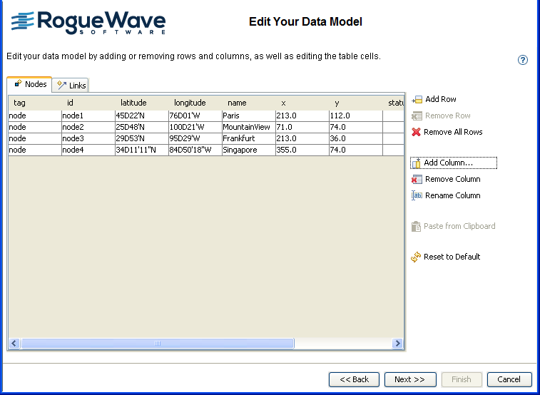
A simple network model in memory
6. Click in the new columns to enter the data values as shown in the following table.
| status | minor | major |
Paris | Available | 2 | 0 |
Mountain View | Unavailable | 4 | 2 |
Frankfurt | Available | 0 | 0 |
Singapore | Available | 0 | 1 |
7. Click Next to select the type of diagram.
8. Select the X/Y Diagram option.
9. Click Finish to exit the wizard.
10. Click File > Save As and save the network diagram as network.idpr.
11. Keep this diagram open to use in the next section.
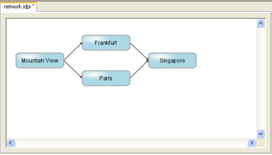
The initial network diagram
Changing the graphic representation of the nodes
You will change the default graphic representation of the nodes in the initial network diagram.
1. Select the node rule in the Style Rules tree.
2. Click Assign Symbol at the bottom of the Styling Customizer.
3. From the Shared Symbols palette, select the NetworkDevice symbol in the Network category.
4. Click Apply.
5. In the Styling Customizer, specify the value @name for the name parameter.
6. Press Enter.
See the following figure.
7. 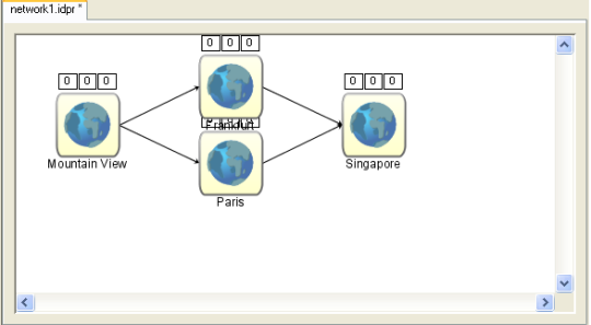
NetworkDevice symbol applied to the diagram
8. Click File > Save As and save the network diagram as network1.idpr.
9. Keep this diagram open to use in the next section.
Copyright © 2018, Rogue Wave Software, Inc. All Rights Reserved.