Inserting an icon
Explains how to load an image file and insert it into a node.

Lists the image file formats supported by the Designer.
Explains how to apply a special symbol to the nodes of the diagram.
Explains how to create style rules associated with different images to represent population ranges.
Explains how to interpret the style rules tree in terms of priority.
Image file formats
You can customize a special symbol to contain an image file.
If you have icons that you want to use to represent your objects, you load the image files through the Styling Customizer.
The image file formats supported by the Designer are as follows:
GIF
JPG
PNG
In the Arizona example, three images are used according to city population:
For cities with fewer than 100 000 residents:
little.gifFor cities with more than 1 000 000 residents:
biga.gifFor the remaining cities (100 000 - 1 000 000 residents):
lightBulb.gif )
Setting a special symbol
To be able to load image files to represent your nodes in the Arizona physical diagram, you must first assign a special symbol to the default graphic representation of the nodes.
To assign a special symbol to the nodes:
1. Click the node rule in the Style Rules pane.
2. Click Assign Symbol at the bottom of the Styling Customizer.
3. Select the Rogue Wave icon
4. 
5. in the Basic category of the Shared Symbols palette.
6. Click Apply.
Creating rules for population ranges
You are going to identify the cities with a different graphic representation according to three specific population ranges.
You need to define three style rules to specify the three conditions on population:
1. Select the node rule and click Edit > Create Style Rule.
a. In the Conditions page, define the condition population exists and not null.
b. Click Finish.
c. With the new population exists and not null rule selected, click the Parameters tab in the Styling Customizer, and type the following path in the image field: file:./data/examples/lightBulb.gif.
d. Press Enter.
2. With the population exists and not null rule selected, click Edit > Create Style Rule.
a. In the Conditions page, click + and define another condition: population is less than 100000.
b. Click Finish.
c. Rename the rule to population<100000.
d. With the new population<100000 rule selected, in the Styling Customizer, type the following path in the image field: file:./data/examples/Little.gif.
e. Press Enter.
3. Select the population exists and not null rule and create the third style rule:
a. Click Edit > Create Style Rule.
b. Click + and define the condition population is greater than 1000000.
c. Click Finish.
d. Rename the style rule to population>1000000.
e. With the new population>1000000 rule selected, type the following path in the image field: file:./data/examples/biga.gif.
f. Press Enter.
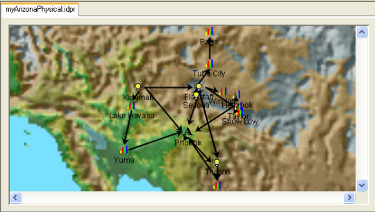
The result is shown in the following figure.
The use of images in the Arizona example
Rule priority
Note that the style rules are displayed in a tree which represents a progressive refinement of styling. As well as the meaning within each style rule, there is also meaning in the tree structure. In fact, the style rules are displayed in ascending order of specificity (least specific at the top of the tree).
The population<100000 rule is more specific than the population exists and not null rule. Therefore the population<100000 rule has priority. The settings in the population<100000 rule override settings in the node rule for all nodes that have population less than 100000.
You can move rules up and down the tree to change their priority, but you cannot place a more specific rule above a less specific one. The commands to move rules are on the Rule Menu which is available when you right-click a rule.
Copyright © 2018, Rogue Wave Software, Inc. All Rights Reserved.