Importing data from a flat file
Explains how to import data from a text file and map it.

Explains how to load the flat file from the New Diagram wizard.
Explains how to import the node data of the flat file.
Explains how to import the link data of the flat file.
Explains how to map properties to node data.
Explains how to map properties to link data.
Explains how to edit the flat file data model.
Explains how to select the diagram type.
Loading the file
The flat file data source allows you to import data from any flat file including a CSV (comma-separated values) file.
To import a flat file:
1. Click File > New from Wizard.
2. Click Next.
3. Select the Flat File option.
See the following figure.
4. 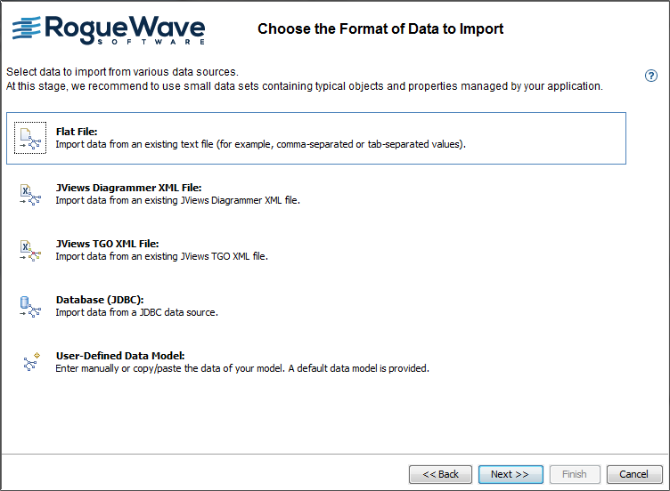
Importing data from a flat file
5. Click Next.
This section uses the Arizona example.
You need to import data for nodes and links separately.
Importing node data
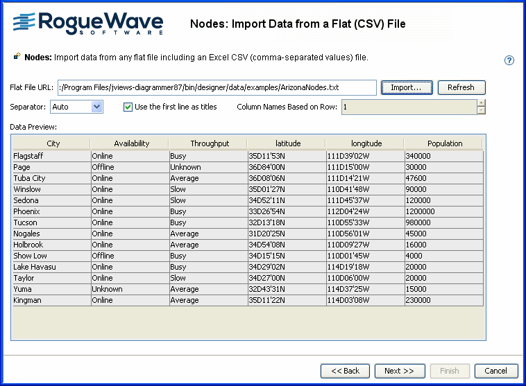
You can choose a separator character and the number of the row containing the column names. The separator character is the character that appears between data values on rows. If you do not change the default settings: Auto and 0 (zero), the Designer tries to interpret the file automatically. If it finds a known separator character, it updates the File Preview on the left.
To import the node data:
1. Click Import and navigate to the ArizonaNodes.txt file.
2. Click Open.
See the following figure.
Importing data on places in Arizona as nodes
Importing link data
You can choose a separator character and the number of the row containing the column names. The separator character is the character that appears between data values on rows. If you do not change the default settings: Auto and 0 (zero), the Designer tries to interpret the file automatically. If it finds a known separator character, it updates the File Preview on the left.
To import link data:
1. Click Next to switch to the Links pane.
2. Click Import and navigate to the ArizonaLinks.txt file.
3. Click Open.
See the following figure.
4. 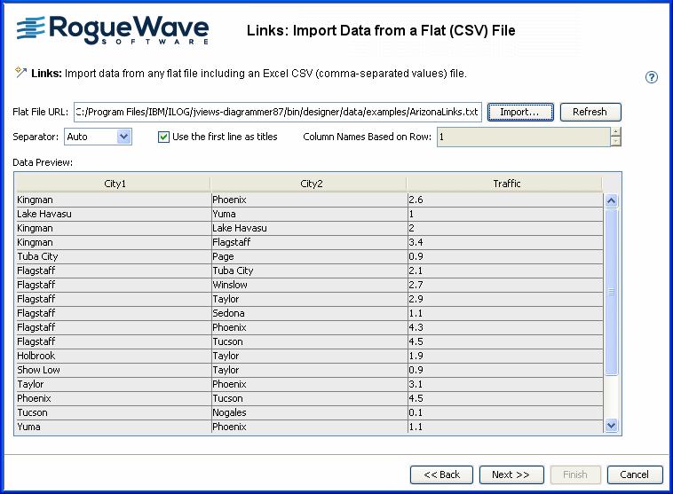
Importing data on traffic between places in Arizona as links
5. Click Next.
Mapping node data
Properties that are not mapped to node data and require to be mapped appear with the following status
in the list of properties, and the same status appears on the Nodes tab. This is the case for the id property. You must map it to a column because its values should uniquely identify the rows.
Additional properties that are not mapped to node data appear with status
in the list of properties.
To map the id property to the City column:
1. Click the id property.
2. Click the City column.
You can map other properties as required.
In this example, you have georeferenced data, so you need to use the latitude and longitude columns to position the nodes. These columns are mapped automatically because of their names. The preferred format for latitude and longitude is DMS (degrees, minutes, seconds). For example: 32D43’31”N. If the latitude and longitude columns contain only numbers, the values are interpreted as degrees. For example: latitude 12.56 is interpreted as 12.56 degrees, which equals 12D33’36”N (in DMS).
To map several properties to the same column:
Map both the
id property and the
name property to the
City column.
To add properties and map them to columns:
1. Click the
1. 
1. button.
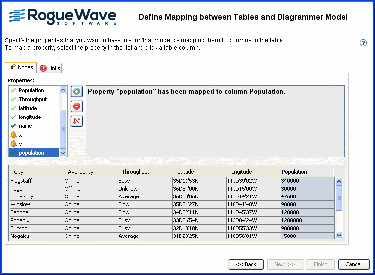
2. Type the property name population.
3. Map this new property to the Population column.
The result is shown in the following figure. Note that with City mapped to name, the name appears on the nodes in the preview.
Mapping node data to properties
To remove the mapping of a property:
1. Select the property in the list.
2. Click the
3. 
4. button.
Mapping link data
You must map the to and from properties to columns because these properties indicate the start and end points of the links. You can map other properties as required.
To map the to and from properties:
1. Click the Links tab.
2. Click the from property then click the column City1.
3. Click the to property then click the column City2.
In this example, the id property is not mapped.
4. 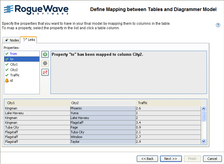
Mapping link data to properties
5. Click Next.
Editing the data model
You can edit the basic data model in the following ways:
Add and remove rows (a row represents an object in the data model)
Add, remove, and rename columns (a column represents a property of the objects in the data model)
Change cell values (a cell represents a property of a specific object)
Remove all objects
Restore the data model to its initial state
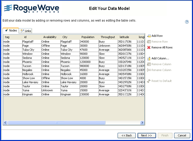
To clear all the data values, click Remove All Rows. To retrieve the values you saw initially, click Reset to Default.
Properties id and tag are mandatory for the SDM model and therefore cannot be removed or renamed by the user.
Editing the flat file data model
Keep this data model as it is.
To validate your data model:
Click
Next.
Selecting the diagram type
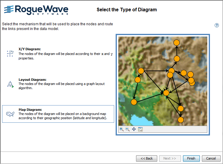
You need to select a diagram type for the correct positioning of the nodes.
Because you have latitude and longitude mapped, the Map Diagram is selected by default, see the following figure.
NOTE If the JViews Maps product is not installed, the X/Y Diagram is selected by default. Click Finish.
Specifying a map diagram
To select the Map diagram:
1. Click Finish.
If you need to make changes, you can click Back instead to return to specific wizard pages.
The resulting diagram is as shown in the following figure.
1. 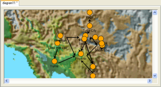
The initial Arizona physical diagram
2. Keep the diagram open to proceed to the next section or save it by clicking File > Save As.
Copyright © 2018, Rogue Wave Software, Inc. All Rights Reserved.