Working in different modes
Explains how to use each of the three modes available in the Designer.

Introduces the three modes.
Explains how to work in Style Editing mode.
Explains how to work in Preview mode.
Explains how to work in Diagram Editing mode.
The three modes
Use the modes in the Designer to develop your diagram as follows:
Work in Style Editing mode to define your
style rules
Work in Preview mode to test the resulting behavior of the diagram component as it would be in an application.
Work in Diagram Editing mode to build up a diagram one node or link at a time, and to position nodes and links in a diagram manually by dragging them. Note that editing the diagram will modify the
data model.
Working in Style Editing mode
In Style Editing mode, you can define styling as follows:
Set options to change some aspect of the diagram as a whole
Create or change a style rule
Select graphic objects and edit the associated style rules
To enter Style Editing mode:
Click the Style Editing button in the vertical toolbar.
Panes in Style Editing mode
In Style Editing mode, the panes of the Designer window are as follows:
Upper left: Style Rules tree, showing the rules that determine the appearance of the objects displayed
Right: Diagram in Style Editing mode
Lower left: Styling Customizer for the selected rule, showing the styling property values.
You can display the data model as a reference if you open the Data Model window.
You can edit the data properties if you open the Data Properties window.
You cannot see all application behavior.
To define a style rule:
Choose
Edit>Create Style Rule to create a new rule with the Create Style Rule wizard
-- or --
Choose
Edit>Change Style Rule to change the selected rule with the Change Style Rule Wizard.
You can also right-click a rule and choose Create Style Rule or Change Style Rule in the pop-up menu.
To select a graphic object in the diagram:
Click the object in the Diagram pane.
A rectangular dashed line appears around it. This is called the
selection box.
To deselect objects:
Click in the pane, outside the objects.
If you select a rule in the Rule Tree, the rule is highlighted and all objects affected by the rule are selected in the diagram.
When a rule is highlighted, the Designer displays the Styling Customizer for the selected object(s).
Selection drives the property setting process as follows:
When you select an option in the Style Rules, the Styling Customizer displays the associated properties.
There can be several rules controlling a data object. When you select an object in the diagram, the Designer highlights the first rule for this object in the Style Rules. The first rule is the most specific one. This action is known as
rule-select. If you click the same object again, the Designer highlights the second rule (second most specific) and so on, that is, it cycles through the rules from the most specific to the least specific and then back to the most specific again. At the same time, the Designer displays the associated properties in the Styling Customizer.
If you double-click a graphic object in the diagram, the objects properties are displayed in the Data Properties window. You can change the values of the properties, except the tag property (user-defined type).
To change a property value:
1. Click the name of the property.
2. Edit the value field of the property.
Working in Preview mode
Preview mode allows you to see application behavior that you do not see in other modes, for example, it shows tooltips and Info Balloons if you have set any.
In Preview mode, you cannot change the style rules or the data model.
Click the Preview button in the vertical toolbar to enter Preview mode.
Panes in Preview mode
In Preview mode, a single pane is displayed containing your diagram.
Working in Diagram Editing mode
In Diagram Editing mode you can insert nodes and links into a diagram and then position them. You can drag objects to new positions and change the way they are interconnected. When you update the diagram manually in this mode, the
data model is automatically updated to remain synchronized with your diagram. For example, the data model changes to reflect new positions if you have a Map Diagram or an X/Y Diagram; the data model changes to reflect differences in interconnections.
In Diagram Editing mode, you cannot change the style rules nor see all application behavior.
To enter Diagram Editing mode:
Click the Diagram Editing button in the vertical toolbar.
Panes in Diagram Editing mode
In Diagram Editing mode, the panes of the Designer window are as follows:
Upper left: Data Model tree, showing the model objects displayed
Right: Diagram in Diagram Editing mode
Lower left: Data Properties of the selected object, showing the current values.
Selection in Diagram Editing mode
If you select objects in the tree or the diagram, they are displayed in the diagram according to the style rules you have defined that govern selection (if any). For example, if you have specified in a rule that a certain type of object should change color when selected by a user of your application, you will see this result when you select an object of that type. If you right-click an object, you can switch the selected/deselected state of the object.
Diagram and data model modification
You can select a type of node from the right end of the horizontal toolbar and drop it onto the diagram. You can select a type of link and click its source node and destination node to create a link. Effectively, you add objects to your
data model when you drop them onto the diagram.
Some data models are not editable, for example, data models derived from JDBC data sources. You cannot edit the diagram in this case.
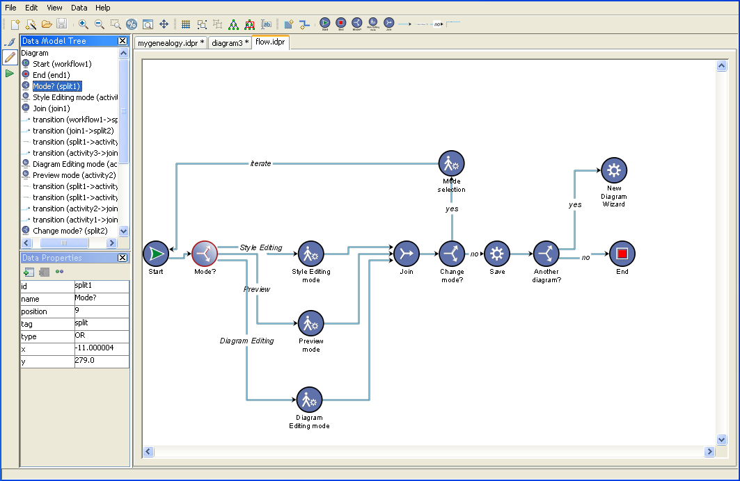
The following figure shows a flow diagram. This example is available as project file flow.idpr.
The flow diagram developed in Diagram Editing mode
To add a node:
1. Click the node icon in the horizontal toolbar.
2. Click anywhere in the diagram.
For example, to add a manual activity, click the manual activity icon
in the toolbar and then click below the existing manual activities in the flow diagram.
In addition to the nodes available from the toolbar, you can create new types of node.
To create a new type of node:
1. Click the Create New Type of Node icon
1. 
1. in the toolbar.
2. Enter the type of the new node in the dialog.
3. Click OK.
The style of the new node is defined by the type set for the node. If no rule has been set for this node type, then the rule “ node ” applies alone.
To move a node:
1. Click the node and drag it to a new position.
Any links attached to the node remain attached.
2. If it is useful, you can perform a layout on all the nodes or a selected subset of them, according to the layout algorithm currently configured in the style sheet.
To add a link:
1. Click the link icon in the horizontal toolbar.
2. Click one node in the diagram (source node).
3. Click another node (destination node).
For example, in the flow diagram, click the good link icon in the toolbar, then click the Mode? node and then click the new manual activity node.
In addition to the links available from the toolbar, you can create new types of link.
To create a new type of link:
1. Click the icon
1. 
1. in the toolbar.
2. Enter the type of the new link in the dialog.
3. Click OK.
The style of the new link is defined by the type set for the link. If no rule has been set for this link type, then the rule “ link ” applies alone.
To move a link:
Click the end you want to detach and drag it to a different node.
The other end of the link remains attached as before.
If you perform a layout on all the nodes or a selected subset of them, affected links will change their routes.
To add a user-defined type:
1. Select a node.
2. Click the Set User-Defined Type button in the Data Properties toolbar.
3. Enter new values for the properties of the user-defined type.
Note that the tag property remains fixed and, instead, your user-defined type is identified by the value of the CSSclass property.
If you switch back to Style Editing mode and create a style rule specifying the appropriate tag value and CSSclass value, you can select a different icon in the Styling Customizer to represent the new user-defined type.
When you add a user-defined type, its icon is added to the horizontal toolbar in Diagram Editing mode automatically.
To add a new property to a type of node or link:
1. Click the New Property button in the Data Properties toolbar.
2. Enter the name and value of the new property.
To remove a property of a type of node or link:
1. Select the property in the Data Properties pane.
2. Click the Delete Property button in the Data Properties toolbar.
Copyright © 2018, Rogue Wave Software, Inc. All Rights Reserved.