For Experts: Further Tips and Tricks
Here are more featured items for using Tree Layout:
East-West Neighbors
You can specify that two unrelated nodes must be directly neighbored in a direction perpendicular to the flow direction. In level or radial layout mode, both nodes are placed in the same level next to each other. In free layout or tip-over mode, both nodes are placed aligned at the north border. Such nodes are called
east-west neighbors, because one node is placed as the direct neighbor on the east side of the other node (and the other node becomes the direct neighbor on the west side of the first node). See also
Compass Directions).
Technically, both nodes are treated as parent and child, even if there may be no link in between. Therefore, one of the two nodes can have a real parent, but the other node should not, because its virtual parent is its east-west neighbor.
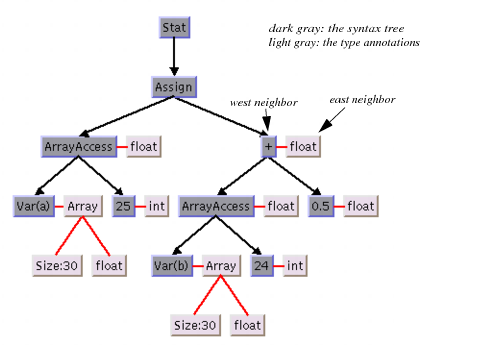
This feature can be used, for example, for annotating nodes in a typed syntax tree occurring in compiler construction.
Figure 4.20 illustrates the usage.
Figure 4.20 Annotated Syntax Tree of Statement a[25] = b[24] + 0.5;
Use the following method to specify that two nodes are east-west neighbors:
You can also use the following method, which is identical except for the reversed parameter order:
If the flow direction is to the bottom, the latter method may be easier to remember, because in this case west is to the left of east in the layout, similar to the text flow of the parameters.
To obtain which node is the east or west neighbor of a node, call:
Note that each node can have maximally one east neighbor and one west neighbor, because they are directly neighbored. If more than one direct neighbor is specified, it will be partially ignored. Cyclic specifications can cause conflict as well. For instance, if node B is the east neighbor of node A and node C is the east neighbor of B, then node A cannot be the east neighbor of C. (Strictly speaking, such cycles could be technically possible in some situations in the radial layout mode, but nonetheless they are not allowed in any layout mode.)
If
B is the east neighbor of
A, then
A is automatically the west neighbor of
B. On the other hand, the east neighbor of
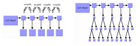
A can itself have another east neighbor. This allows creating chains of east-west neighbors, which is a common way to visualize lists of trees. Two examples are shown in
Figure 4.21.
Figure 4.21 Chains of East-West Neighbors to Visualize Lists of Trees
Retrieving Link Categories
The Tree Layout Algorithm works on a spanning tree, as mentioned in a
Brief Description of the Algorithm. If the graph to be laid out is not a pure tree, the algorithm ignores some links. In order to perform a special treatment of such links, it is possible to obtain the list of non-tree links.
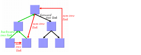
There are parents and children in the spanning tree. We distinguish the following link categories:
 Forward tree link
: a link from a parent to its child.
Backward tree link: a link from a child to its parent. If the link is drawn as a directed arrow, the arrow will point converse to the flow direction.
Non-tree link: a link between two unrelated nodes; neither one is a child of the other.
Figure 4.22 Link Categories
The layout algorithm uses these link categories internally but does not store them permanently for the sake of time and memory efficiency. If you want to perform a special treatment on some link categories (for example, to call the Orthogonal Link Layout on the non-tree links), you must specify
before layout that you want to access the link categories
after layout. In order to do this, use the method
setCategorizingLinks in the following way:
layout->setCategorizingLinks(IlTrue);
// now perform a layout
layout->performLayout();
// now you can access the link categories
After layout, the link categories are available in three lists that can be obtained by these methods:
These lists get filled each time the layout is called, unless you switch categorizing links back to IlFalse.
Note that the returned lists are constant. You should not change them directly. However, you can iterate over the lists and retrieve the links of each category, for example, to perform a special operation for non-tree links:
IlvLink* link = layout->getCalcNonTreeLinks()->getFirst();
while (link) {
linkimage = (IlvLinkImage*)link->getValue();
link = link->getNext();
// ... perform special operation with linkimage
}
Sequences of Layouts with Incremental Changes
You can work with trees that become out-of-date from time to time, for example, those that need to be extended with more children. If you perform a layout after an extension, you probably want to identify the parts that were already laid out in the original graph. The Tree Layout Algorithm supports such incremental changes because it takes the previous positions of the nodes into account. It preserves the relative order of the children in the next layout.
Interactive Editing
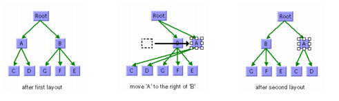
The fact that the relative order is preserved is particularly useful during interactive editing. It allows you to easily correct the layout. For instance, if the first layout places a node A left to its sibling B but you need it in reverse order, you can simply move A to the right of B and start a new layout to clean up the drawing. In this second layout, A will stay to the right of B, and the subtree of A will “follow” node A.
Figure 4.23 Interactive Editing to Achieve Specific Order of Children
Specifying the Order of Children
Some applications require a specific relative order of children in the tree. That means, for instance—with flow direction to the bottom—which child must be placed to the left of another child. Even if the graph was never laid out, you can use the coordinates to specify a certain order of the children at a node in the following way:
In free or level layout mode with flow direction to the bottom or top, determine the maximal width “
W” of all nodes. Simply move the child that should be leftmost to the coordinate
(0, 0), and the child that should get the
ith relative position (in order from left to right) to coordinate
((W+1)*i, 0).
If the flow direction is to the left or to the right, determine the maximal height
H of all nodes. Move the child that should be topmost to the coordinate
(0, 0), and the child that should get the
ith relative position (in the order from top to bottom) to coordinate
(0, (H+1)*i).
In the radial layout modes, determine the maximal diagonal
D = W2 + H of all nodes. If the position of the parent is
(x, y) before layout, then move the child that should be the first in the circular order to the coordinate
(x, y+D), and the child that should get the
ith relative position in the circular order to coordinate
(x+D*i, y+D).
If you want to specify a relative order for all nodes in radial mode, you must do this for the parents before you do it for the children. In this case, the movements can be easily performed during a depth-first traversal from the root to the leaves.
The layout that is performed after the movement arranges the children with the desired relative order.
Version 6.0
Copyright © 2015, Rogue Wave Software, Inc. All Rights Reserved.