IPWAVELET Function (PV-WAVE Extreme Advantage)
Computes the separable wavelet transform for an image.
Usage
result = IPWAVELET(image, qmfilt, n_stages[,direction])
Input Parameters
image—A 2D or 3D array containing an image; or image, row, or pixel-interleaved images.
qmfilt—A 1D quadrature mirror filter designed using the IPQMFDESIGN function.
n_stages—The number (greater than or equal to 1) of wavelet transform stages to perform.
direction—(optional) A scalar indicating the direction of the transform as follows:
– 1 Forward transform (default)
1 Backward transform
Returned Value
result—A 2D or 3D double array containing the wavelet transform.
Keywords
Intleave—A scalar string indicating the type of interleaving of 3D input image arrays. Valid strings and the corresponding interleaving methods are:
'pixel'—The input array arrangement is (p, x, y) for p pixel-interleaved images of x-by-y.
'row'—The 3D image array arrangement is (x, p, y) for p row-interleaved images of x-by-y.
'image'—The 3D image array arrangement is (x, y, p) for p image-interleaved images of x-by-y.
Discussion
Computing the wavelet transform of an image using a compactly supported orthonormal wavelet is equivalent to applying the quadrature mirror filter-bank structure to the image as shown in Forward Wavelet Transform Filter Structure .
|
|
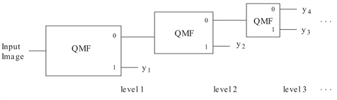
The details of how and why the structure shown in the figure is connected to a compactly supported orthonormal wavelet are found in Akansu and Haddad, 1992; Daubechies, 1988, and 1992; Rioul and Vetterli, 1991; and Vaidyanathan, 1993.
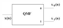
The input and output sequences of each block in the figure represent the inputs and output of the forward part of the quadrature mirror filtering technique. The specific input-output relation between each block and the quadrature mirror filter is shown in Forward Wavelet Transform Computational Cell.
|
|
IPWAVELET requires a quadrature mirror filter to be supplied. Such a filter is obtained by using the IPQMFDESIGN function.
The input parameter n_stages specifies the number of levels of the wavelet transform structure to compute.
The backwards wavelet transform is computed using the filter bank structure shown in Backward Wavelet Transform Filter Structure.
|
|

Example
This example illustrates how to compute the wavelet transform of an image.
; Read an image.
image = IMAGE_READ(!IP_Data + 'blobs.tif')
qmfilt = IPQMFDESIGN(Daubechies = 4)
; Compute the 2-stage forward wavelet transform with the
; Daubechies 4 wavelet.
wvlt = IPWAVELET(image('pixels'), qmfilt, 2, -1); Display the wavelet transform.
TVSCL, wvlt
; Compute the inverse transform.
iwvlt = IPWAVELET(wvlt, qmfilt, 2, 1)
; There will be some distortion due to machine noise.
wvlt_error = iwvlt - image('pixels')PRINT, MAX(wvlt_error)


