Z‑buffer Output
The Z-buffer allows you to create complex 3D plots, image warping to polygons, and transparency effects without special hardware.
To direct graphics output to the Z-buffer, enter the command:
SET_PLOT, 'Z'
This causes PV‑WAVE to use the Z-buffer driver for producing graphical output. Once the Z-buffer driver is enabled via SET_PLOT, the DEVICE procedure is used to control its actions, as described in
"Controlling Z-buffer Output with DEVICE Keywords".
Use INFO, /Device to view the driver’s current settings.
Controlling Z-buffer Output with DEVICE Keywords
The following keywords to the DEVICE procedure provide control of the Z-buffer driver:
Close—Deallocates the memory used by the buffers. The Z-buffer device is reinitialized if subsequent graphics operations are directed to the device.
Get_Graphics_Function—See the description of the
Get_Graphics_Function keyword in
"Controlling X Driver with DEVICE Keywords".
Get_Write_Mask—See the description of the
Get_Write_Mask keyword in
"Controlling X Driver with DEVICE Keywords".
Set_Character_Size—A two-element vector that changes the standard width and height of the vector-drawn fonts. The first element in the vector contains the new character width, and the second element contains the height. By default, characters are approximately 8-pixels wide, with 12 pixels between lines.
Set_Colors—Sets the number of pixel values, !D.N_Colors. This value is used by a number of routines to determine the scaling of pixel data and the default drawing index. Allowable values range from 2 to 256, and the default value is 256. Use this parameter to make the Z-buffer device compatible with devices with fewer than 256 color indices.
Set_Graphics_Function—See the description of the
Set_Graphics_Function keyword in
"Controlling X Driver with DEVICE Keywords".
The Z-buffer allows you to use all graphics functions supported by the X driver.
Set_Resolution—Two-element vector that sets the width and height of the buffers. The default size is 640-by-512. If this size is not the same as the existing buffers, the current buffers are destroyed and the device is reinitialized.
Set_Write_Mask—See the description of the
Set_Write_Mask keyword in
"Controlling X Driver with DEVICE Keywords".
Z-buffer Examples
Example 1
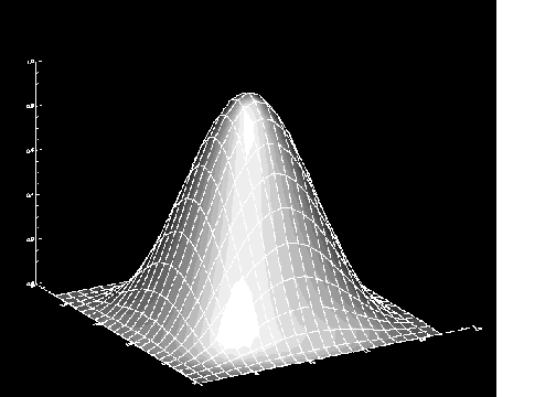
This example demonstrates how graphics can be rendered in memory (into the Z-buffer) and then later displayed. The resulting image is shown in
Image Rendered from Z-Buffer.
SET_PLOT, 'z'
SHADE_SURF, HANNING(23,23)
SURFACE, HANNING(23,23), /Noerase
img = TVRD(0,0,640,512)
SET_PLOT, 'x'
TV, img
Example 2
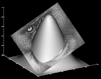
This example creates a single image composed of two intersecting objects drawn with hidden surfaces removed. This effect can only be accomplished with the Z-buffer. The resulting image is shown in
Figure B-7: Image Composed of two Intersecting Objects on page 2131.
; Remember current graphics device
dev_name = !D.Name
im = BYTARR(512,512)
; Open the file containing the image.
OPENR, 1, FILEPATH('mandril.img', SubDir='data' )READU, 1, im
CLOSE, 1
SET_PLOT, 'z'
; Erase the Z-buffer in case there was something in there before.
ERASE
; Draw a surface. Remember the 3D viewing transform (/Save).
SHADE_SURF, HANNING(23,23), /Save
; Create a 3D quadrilateral in data coordinates.
verts=[ [0,0,0], [20,0,0.5], [20,20,1], [0,20,0.5] ]
; Draw the transformed quadrilateral with an image mapped
; onto it.
POLYFILL, Verts, Pattern = im, $
Image_coord=[[0,0],[511,0],[511,511], [0,511]], /T3d
res = TVRD(0,0,640,512)
SET_PLOT, dev_name
TVSCL, res
; Notice how the two objects intersect.
Example 3
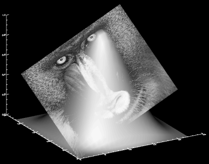
In this example, the same image from the previous example is created; however, this time maximum intensity projection is used to produce a transparency effect. The resulting image is shown in
Image with Transparency Effect.
; Remember current graphics device
dev_name = !D.Name
im = BYTARR(512,512)
OPENR, 1, FILEPATH('mandril.img', SubDir='data' )READU, 1, im
CLOSE, 1
SET_PLOT, 'z'
; Erase the Z-buffer in case there was something in there before.
ERASE
; Draw a surface.
; Remember the 3D viewing transform (/Save).
SHADE_SURF, HANNING(23,23), /Save
; Create a 3D quadrilateral in data coordinates.
verts=[ [0,0,0], [20,0,0.5], [20,20,1], [0,20,0.5] ]
; Draw the transformed quadrilateral with an image mapped onto
; it.
POLYFILL, Verts, Pattern = im, $
Image_coord=[[0,0],[511,0],[511,511], [0,511]], /T3d, /Mip
res = TVRD(0,0,640,512)
SET_PLOT, dev_name
; Notice how the two objects interact this time. You can partially
; see through the surface to the image passing through it.
TVSCL, res
Version 2017.0
Copyright © 2017, Rogue Wave Software, Inc. All Rights Reserved.


