Graphic Representation of the Behavior of a Prototype
In the examples that illustrate each behavior class, the data flow defined by the accessors of a prototype is represented using the following graphic vocabulary:
-
A rectangle represents an accessor (elementary piece of behavior).
-
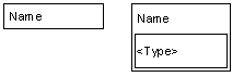
An attribute is represented by a stack of accessors with a given name. In such a stack, the accessors are evaluated from top to bottom when the value of the attribute is changed or queried.
-
The order of evaluation is represented by the relative position of an accessor in its stack.
-
An inset rectangle is used to represent the type of the given attribute.
A graphic representing these items is shown here:
Also:
-
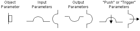
Slots on the sides of accessors represent the parameters of the accessor.
-
A round slot represents a value parameter.
-
A square slot represents an object parameter.
-
Slots at the top represent the input access to a value.
-
Slots at the bottom represent its output.
-
Slots on the left side represent input parameters of the accessors (the accessors will query their value when they are evaluated).
-
Slots on the right side represent output parameters (the accessors will change the values).
-
Finally, slots with an arrow indicate that the value will be pushed instead of simply set. The arrow is used to indicate Trigger accessors.
A graphic representing these items is shown here:
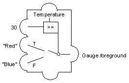
To complete the model, links or direct values are used to connect the accessor output to other input attributes. The following diagram shows a Condition accessor with these conditions. If Temperature is set to above 30, the foreground of the Gauge object will be set to Red. Otherwise, it will be set to Blue.