Creating the Domain Nodes Panel
This section explains how to create the Domain Nodes panel of the Network application.
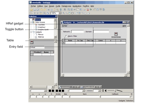
As you can see from the illustration below, this panel contains:
-
A table that represents the nodes of a given network domain with their input and output capacities, a hyper-reference to the Lines of Node panel, and two variables x and y that display the node coordinates. If you have a color monitor, you can see that nodes appear in different colors. The color of each node depends on the difference between its input capacity and its output capacity:
-
If its input capacity is greater than its output capacity, the node appears red and is in an alarm state.
-
If its output capacity exceeds its input capacity, the node appears blue.
-
When the load is balanced, the node takes a green color.
-
-
An Alarm Filter toggle button to filter the nodes that are displayed in the table.
Final Domain Nodes Panel
When finished, this panel will look like this in the Main window:
Domain Nodes Panel in the Main Window
Following is the list of operations you are going to perform to create the Domain Nodes panel:
-
Create the DomainNodes view,
-
Define the Main and Properties data sources related to the DomainNodes view,
-
Fill in the data source table with values,
-
Add a parameter to the DomainNodes view,
-
Create a hyper-reference to the Network panel,
-
Associate a gadget with the Properties data source,
-
Change a cell color according to a conditional expression,


