Applying Conditions to Representation Objects
You can apply conditions to representation objects—both to the table and to the row —to filter the server objects that will be displayed in the final graphic panel.
Let us suppose that you want to use colors to indicate which state a particular node is in and then filter nodes to show only those that are in an alarm state.
You must first define an expression to specify under which conditions the color of a node varies. You will then have to set the condition that will be used to filter the nodes. Conditions are expressions that can contain view parameters.
In this section, you will learn how to:

Change the color of a cell depending on certain conditions.

Set a view parameter.

Filter the nodes to be displayed according to the state of the view parameter.

Associate a toggle button with a view parameter.
Changing a Color Cell According to an Expression
As explained in
Representation Object Attributes, a representation object attribute can be defined by an expression. Thus, we can associate an expression that specifies how the color of a node should vary with the cell in which the name of a node appears, as follows:
1. If necessary, open the Server Data Source inspector again and click on the Table page in the notebook section of the Server Data Source inspector to bring it to the foreground.
Reminder: The Main data source table for the DomainNodes view lets you define attributes related to the class Node (nodes are represented as rows in the table).
2. In the column “Node”, double-click on the cell that contains the name attribute.
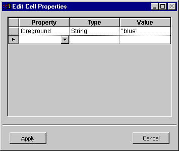
The Edit Cell Properties dialog box opens. This dialog box lets you modify the foreground and background color of a table cell, which are predefined cell properties.
Edit Cell Properties Dialog Box
3. Use the Property combo box menu to select background and type "red" in the Value column.
Be sure to type the quotes, which indicate that the result is a string literal and not an expression or an attribute name.
4. Click in the Value column cell again to fill it with this expression:
((inputCapacity>outputCapacity)?"red":
((inputCapacity<outputCapacity)?"cyan":"green"))
This expression specifies that a node will appear in red if its input capacity exceeds its output capacity, in blue if its input capacity is smaller than its output capacity, and in green if the load is balanced. Because the row represents a Node object, the expression in the Value column can reference all the Node attributes, as well as all the attributes of all the classes that can be reached through a unary relation of Node.
5. Click Apply in the Edit Cell Properties dialog box.
The cell in the data source table changes to grey, indicating that the cell has one or more properties set.
6. The color of a node will change according to this expression.
The gray box below list the valid operators you can use in expressions.
Valid Operators in Expressions These operators are allowed in conditions: == Equal to != Not equal < Less than > Greater than <= Less than or equal to >= Greater than or equal to || Logical or && Logical and You can also use an expression of the form: (expression)?(v):(v) |
Adding a Parameter to the DomainNodes View
You can associate parameters with a view. Parameters let you modify the attributes of a representation object without modifying the related server object. They also make it possible to filter the server objects to be displayed in a graphic panel.
In this section, we are going to define the onlyAlarm parameter that will be used to activate or deactivate node filtering.
1. Expand one of the classes in the top pane of the inspector and select the relation view.
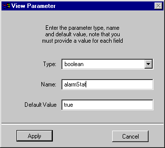
2. Click on view with the right mouse button and choose Add View Parameter from the context-sensitive pop-up menu. The following dialog box appears:
View Parameter Dialog Box
3. Select Boolean as the parameter type, enter onlyAlarm as the attribute name and enter false as the default value.
Important: These three fields are mandatory. The view parameter will not be created if one of the fields is left empty. |
4. Click Apply.
The dialog box closes. The parameter now appears whenever you select the relation view from any class in the top pane of the inspector panel. Note that you can delete any user-defined view parameters by selecting the parameter and pressing the Delete key.
5. Click on the Properties page in the notebook to bring it to the foreground.
6. Drag the onlyAlarm parameter from the top pane to the empty row of the table.
The parameter type, Boolean, is set automatically.
7. Type alarmStat in the Property column to replace the string onlyAlarm that was inserted by the drop.
The Properties table now looks like this:
View Parameter Displayed in the Properties Table
8. In the final application, the node filtering will be activated if the alarmStat parameter is set.
Setting a Condition to Filter the Nodes
To filter the nodes that appear in the DomainNodes panel and show only those that are in an alarm state, you have to associate the condition (inputCapacity>outputCapacity) with their representation object, that is, with a row.
1. Click on the Conditions page in the notebook to bring it to the foreground.
2. On the row for the Node (called row), type the following expression in the Value column:
((view.onlyAlarm==false)||(inputCapacity>outputCapacity))
3. Click Apply.
If the onlyAlarm parameter is false, all nodes are displayed. If it is true, the nodes are filtered to display only those that show an alarm.
Here is what you should obtain.
Filtering Condition Displayed on Conditions Notebook Page
You have just defined a representation condition that determines whether this row should be created or not.
Note: Conditions can also be applied to the relations touched by propagation.
For example, if you want the DomainNodes view to be opened with only certain nodes displayed, type the appropriate condition in the row Domain::nodes. |
Version 6.3
Copyright © 2018, Rogue Wave Software, Inc. All Rights Reserved.


